Micro-Scallop Robot

Nanobots Swim Like Scallops In Non-Newtonian Fluids

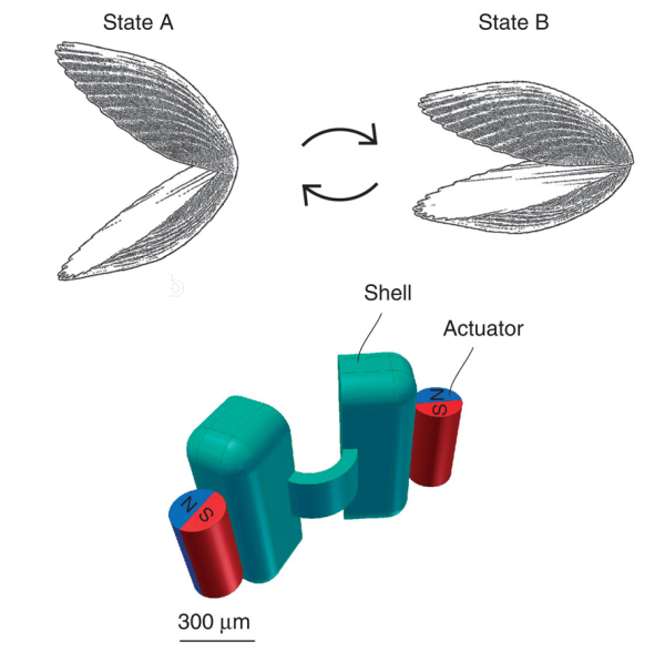
The idea of using nanobots to treat diseases has been around for years, though it has yet to be realized in any significant manner. Inspired by Purcell’s Scallop theorem, scientists from the Max Planck Institute for Intelligent Systems have created their own version . They designed a “micro-scallop” that could propel itself through non-Newtonian fluids, which is what most biological fluids happen to be.

The scientists decided on constructing a relatively simple robot, one with two rigid “shells” and a flexible connecting hinge. They 3D-printed a negative mold of the structure and filled it with a polydimethylsiloxane (PDMS) solution mixed with fluorescent powder to enable detection. Once cured, the nanobot measured 800 microns wide by 300 microns thick. It’s worth noting that it did not have a motor. Once the mold was complete, two neodymium magnets were glued onto the outside of each shell. When a gradient-free external magnetic field was applied, the magnets make the nanobot’s shells open and close. These reciprocal movements resulted in its net propulsion through non-Newtonian media. The scientists also tested it in glycerol, an example of a Newtonian fluid. Confirming Purcell’s Scallop theorem, the nanobot did not move through the glycerol. They took videos of the nanobot in motion using a stereoscope, a digital camera with a colored-glass filter, and an ultraviolet LED to make the fluorescent nanobot detectable.

The scientists did not indicate any further studies regarding this design. Instead, they hope it will aid future researchers in designing nanobots that can swim through blood vessels and body fluids.  We don’t know how many years it will be before this becomes mainstream medical science, but we know this much: we will never look at scallops the same way again!

Continue reading “Nanobots Swim Like Scallops In Non-Newtonian Fluids”

Create A Buzz With The Mini Electric Ukulele

Everyone’s heard of the “World’s Smallest Violin,” but we think it’s time for something more upbeat. [Simone Giertz] of Punch Through Design has created a mini electric ukulele using a LightBlue Bean. The Bean is an Arduino-compatible microcontroller that you can wirelessly program using Bluetooth low energy (BLE).

The ukulele’s frame is made of laser-cut plywood.  Four 1M ohm resistors are soldered to individual wire strings. A different set of wire strings in the ukulele’s neck are connected to the same ground as the Bean. In order to play this tiny instrument, a finger must be kept on the “ground” strings while the other “tone” strings are touched by a different finger. [Simone] uses Arduino’s Capacitive Sensing Library to determine which string is being touched and what the tone will be (indicated in Hz). A piezo buzzer provides the sound. There is no need to fret when the battery is depleted from using this at an all-night luau: the frame can be unscrewed with easy access to the battery. [Simone] has uploaded the Bean’s code to GitHub.

There’s no shame going solo, but we’d enjoy a show of dueling mini-ukuleles. A duet with the 3D-printed ukulele is always a possibility. Or, play this little guy while running up and down some piano stairs while the kettle fife blows off some steam.  It’ll be a musical way to brighten anyone’s day. Check out the video of the mini ukelele after the break. You can also see more of [Simone’s] work at her website.

Continue reading “Create A Buzz With The Mini Electric Ukulele”

Pumpkin with a motion detector to deter squirrels

Scare Off Squirrels And Tweet About It With The Jack-O’-Lantern Warning System

[Stephpalm] had carved a pumpkin for the first time in two decades. Unfortunately, the neighborhood squirrels were all too pleased with her work and devoured it. Her original goal for the jack-o’-lantern was to have its lights controlled over the internet. These hungry critters inspired another project instead – The Jack-’o’-Lantern Squirrel Early Warning System. There have been hacks that have dealt with pesky squirrels before, such as a trap and an automatic water turret, but they didn’t have the ability to post to social media like this system does.

The system consists of a Spark Core, a passive infrared (PIR) sensor, and a piezo buzzer. When the motion sensor is triggered the buzzer sounds, scaring away any peckish creatures lurking nearby. [Stephpalm] used an NPN transistor and 1k-Ohm resistor to provide enough current to drive the buzzer. All of these components were connected using jumper wires and a breadboard that sits on top of the pumpkin. As a nod to her original idea, [stephpalm] then created “Pumpkin Watch Code” and loaded it into the Core. It posts preset messages to a Twitter account every 45 minutes of inactivity or whenever a pesky squirrel is detected. The messages can be personalized for anyone who wants to make one of these themselves.

We wonder if it would be better to place the breadboard inside the jack-o’-lantern and carve out a couple of holes on top for the PIR sensor’s wires to come out of. That would offer some protection from the elements and prevent it from getting knocked over. We think this project could be adapted for many other uses. After the break, see a video of the system in action!

Continue reading “Scare Off Squirrels And Tweet About It With The Jack-O’-Lantern Warning System”

Wireless Warning Sign

Bluetooth-Enabled Danger Sign For Lab

[A Raymond] had some free time at work, and decided to spend it on creating a wireless warning sign. According to his blog profile, he is a PhD student in Applied Physics. His lab utilizes a high-powered laser system. His job is to use said system, but only after it’s brought online by faculty scientists. The status of the laser system is changed by a manual switchbox that controls the warning signs wired around the lab entrances. Unfortunately, if you were in the upstairs office, you only knew this after running downstairs to check. [A Raymond’s] admitted laziness finally got the better of him – he wanted a sign that displayed the laser’s status from the comfort of the office. He had an old sign he could use, but he wanted a way for it to communicate with the switchbox downstairs. After some thought, he decided Bluetooth was the way to go, using a pair of BlueSMiRF Bluetooth modules from Sparkfun and Arduino Uno R3’s.

He constructed a metal box that intercepted the cable from the main switchbox, mounting one BlueSMiRF and Uno into it. Upon learning that the switchbox sends 12V AC signals over three individual status wires, he half-wave rectified the wires and divided their voltages so that the Uno wouldn’t fry. Instead, it determined which status wire that had active voltage. and sent a “g(reen)”, “y(ellow)”, or “r(ed)” signal continuously via Bluetooth. On the receiving end, [A Raymond] gutted the sign and mounted the other BlueSMiRF and Uno into it along with some green, yellow, and red LEDs. The LEDs light up in response to the corresponding Bluetooth signal.

The result is a warning sign that is always up-to-date with the switchbox’s status. We’ve covered projects using Bluetooth before, from plush birds to cameras– [A Raymond’s] wireless sign is in good company. He notes that it’s “missing” a high pitched whining noise when the “Danger” lights are on. If he decides to add an accompanying (annoying) sound, he couldn’t go wrong with something like this. Regardless, we’re sure [A Raymond] is happy that he no longer has to go back and forth between floors before he can use the laser.

Developers posing with the J-Deite Quarter

Meet J-Deite Quarter, The 4-Foot-Tall Transformer

There’s just something about the idea of robots turning into everyday objects that fascinates us all. It seems Japan outdoes the world in that category, and the J-Deite project is no exception. J-Deite Quarter is the first transforming robot to come from the collaborative project between  [Kenji Ishida] of Brave Robotics, [Watur Yoshizaki] of Asratec Corp., and Tomy Co. Ltd. If Brave Robotics sounds familiar, that’s because this isn’t the first transforming robot [Kenji Ishida] has produced, nor the first featured on Hackaday.

The J-Deite Quarter weighs 77lbs (35kg) and can run for an hour on a single battery charge. It’s joints are powered by Futaba servos. It is controlled by the proprietary V-SIDO OS designed by [Watur Yoshizaki]. As a robot, it stands at 4.25 feet (1.3m). It walks at a rather slow speed of 0.6mph (1km/hr). It has several points of articulation; it can bend its arms and flex its fingers. In less than 30 seconds, the robot transforms into an equally long two-seat sports car with a maximum speed of just over 6mph (10km/hr). Overall, the J-Deite Quarter is no speed demon, but it is noteworthy for being functional in both forms.

The web site has a cute backstory featuring a green meteorite that allows the “real” J-Deiter to communicate with the developers trying to create a robot in its image. Along with the video, it resembles a marketing ploy for a toy, which could explain Tomy’s involvement. After all, Tomy, along with Hasbro, developed the original Transformers toy line. Unfortunately, the J-Deiter Quarter is just a prototype, with no plans for mass production at this time. Instead, the project’s focus is on making a bigger and better J-Deiter. There are plans for a J-Deiter Half (8-foot-tall) to be developed by 2016, with the final goal of creating a 16-foot-tall transforming robot by 2020.

Enjoy the video that shows what J-Deite Quarter is capable of (with added sound effects, of course) after the break. Now, if you’ll excuse me, I have a sudden hankering to watch some Transformers and Voltron cartoons.

[via SimpleBotics]

Continue reading “Meet J-Deite Quarter, The 4-Foot-Tall Transformer”

Mehdi wth his homemade taser

[Mehdi’s] Shocking Stun Gun Tutorial

[Mehdi Sadaghdar] never lets little things like fire, shocks, or singed fingers get in the way of his projects.  His latest is a tutorial on making a simple electroshock device. A stun weapon creates a very high voltage, and is used in law enforcement to temporarily disable a person. [Mehdi] stresses repeatedly to not use this on anyone. If you do, he won’t like you anymore. Of course, if you’ve seen any of his previous videos, you know he’ll shock himself and set something on fire before the project is complete.

To create his stunner, [Mehdi] used a car ignition to produce a high voltage. The igniton coil, which is a specialized transformer, allowed him to generate the >10000V output needed for the stunner. The coil has a 60:1 ratio and is powered by a 12V DC supply. Since a coil is a short at DC, the system only creates a high voltage pulse when power is disconnected. However, the pulse was too short to create a satisfying arc. [Mehdi] added a capacitor, creating an LC circuit that oscillates as the charge decays, creating a nicer spark. He then used an RC circuit and a relay to create a simple oscillating switch. For the finishing touch, he created a spark gap on the secondary of the transformer with two nails. In typical [Mehdi] fashion, he nearly fried his digital caliper in the process.

The end result is a nice spark that warms the cockles of [Mehdi’s] fibrillating heart. We commend him for being such a brave masochist in the name of science.  Check out his tutorial after the break!

Continue reading “[Mehdi’s] Shocking Stun Gun Tutorial”

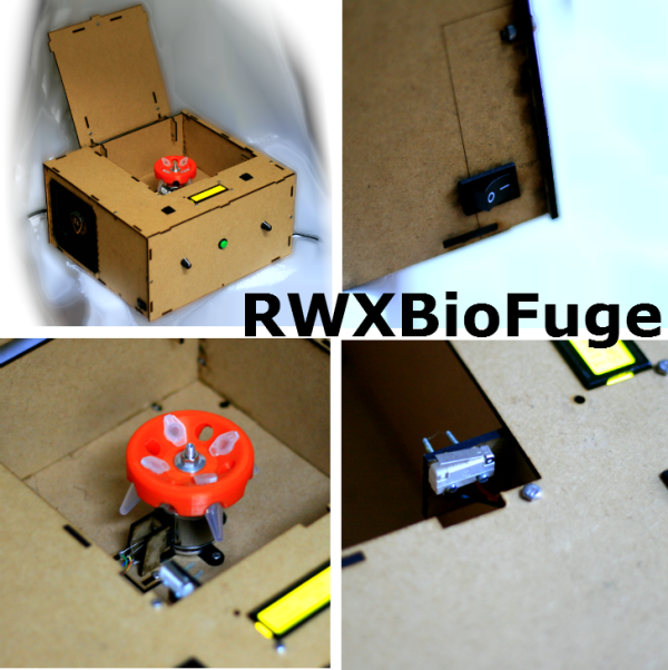
RWXBioFuge collage v0.1

Take Your Samples For A Spin With The RWXBioFuge

We have a confession to make: we love centrifuges. We’ve used all shapes and sizes, for spinning bags of whole blood into separate components to extracting DNA, and everything in between. Unfortunately, these lab staples are too expensive for many DIY-biologists unless they buy them used or build them themselves. [Pieter van Boheemen] was inspired by other DIY centrifuges and decided to make his own, which he named the RWXBioFuge.

[Pieter] designed the RWXBioFuge using Sketchup, OpenSCAD, and InkScape. It features a Thermaltake SMART M850W ATX power supply, an R/C helicopter Electronic Speed Controller (ESC), and brushless outrunner motor. For user output it utilizes a 16×2 LCD character display with an I2C interface.The frame is laser-cut from 3mm MDF while the 3D-printed PLA rotor was designed with OpenSCAD.

An Arduino handles the processing side of things. [Pieter] used an Arduino Ethernet – allowing a web interface to control the centrifuge’s settings and operation from a distance. We can see this being useful in testing out the centrifuge for any rotor/motor balance issues, especially since [Pieter] states that it can be configured to run >10,000 rpm. We wouldn’t want to be in the room if pieces start flying off any centrifuge at that speed!  However, we feel that when everything’s said and done, you should have a centrifuge you can trust by your side when you’re at your lab bench.

While there are similarities to the Openfuge, the larger RWXBioFuge has rotor capacities of eight to twenty 1.5-2.0ml microcentrifuge tubes. Due to the power supply, it is not portable and a bit more expensive, but not incredibly so. There are some small touches about this centrifuge that we really like. The open lid detector is always a welcome safety feature. The “Short” button is very handy for quick 5-10 second spins.

A current version of the RWXBioFuge is being used at the Waag Society’s Open Wetlab. [Pieter’s] planned upgrades for the next version include a magnetic lid lock, different rotor sizes, an accelerometer to detect an improperly balanced rotor, and optimizing the power supply, ESC, and motor setup. You can never have enough centrifuges in a lab, and we are looking forward to seeing this project’s progress!

Check out a few more pictures of the RWXBioFuge after the break.

Continue reading “Take Your Samples For A Spin With The RWXBioFuge”