Solder Pot From The Kitchen

We aren’t shy of dangerous projects, but, then again, a large cooking pan full of lead solder might be a bit much, even for us. It goes without saying that you should be extremely careful and you won’t want to use any of the cookware again for any other purpose. You can see the build in the video below.

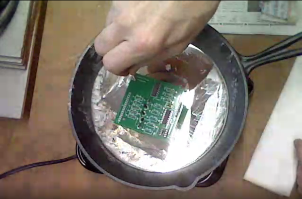
On the one hand, it isn’t hard to make a solder pot. All you need is a container that won’t melt and a heat source. But it seems like molten metal should be in something a little harder to tip over. The real story here is the technique for using the solder pot as the build is dead simple: a cheap hot plate and an iron skillet are all it takes.

Why do you want a solder pot? They are useful. As [Coalpeck] shows, you can use them to dip solder a through hole PCB easily enough. They are great, too, if you want to tin a lot of wires. They also can do a great job of removing parts from a board or a connector. Check out the old, but good video of a commercial unit removing a PCB connector after the main video.

We thought the temperature measurement technique of letting newspaper turn brown was interesting. Granted, a commercial solder pot big enough to be useful isn’t cheap. You can, though, get smaller pots (50-80 mm) for under $50. These will usually have a tray to catch spills and will be harder to tip over by accident. Not that you won’t want to be careful, though. If you do attempt this, we suggest you use a pan with no handle and set it in an outer pan to catch any overflow. But if you spill a few pounds of molten solder on your workbench, don’t say we didn’t warn you.

We’ve covered several homebrew solder pots over the years but, mysteriously, all the original websites are gone. We hope they are OK. We did look at a host of desoldering techniques that include the solder pot. Or ditch the pot of hot lead and try one of [Bil Herd]’s methods.

Continue reading “Solder Pot From The Kitchen”

ESP32: Is Two Better Than One?

We’ve looked at the WROOM-DA module before. It’s an ESP32 with two antennas, and [Andreas Spiess] says it is the ugliest ESP32 he’s ever seen. But beauty is only skin deep, after all. Did [Andreas] find beauty in the twin antennas? Watch the video below and see for yourself.

According to the block diagram, the twin antennas are not used simultaneously but offer diversity one at a time. There is also 8GB 8 MB of flash, double the amount on traditional WROOM modules. Mounting the device was a bit difficult since most ESP32 carrier boards will block some portion of the antenna array.

Continue reading “ESP32: Is Two Better Than One?”

Detailed Big Screen Multimeter Review

It seems like large-screen cheap meters are really catching on. [TheHWcave] does a very detailed review of a KAIWEETS KM601, which is exactly the same as a few dozen other Chinese brands you can get from the usual sources. You can see the review in the video below.

If we learned nothing else from this video, we did learn that you can identify unmarked fuses with a scale. The fuses inside were not marked, so he wanted to know if they appeared to be the right values. We would have been tempted to just blow them under controlled conditions, but we get he didn’t want to destroy the stock fuses until after testing.

Continue reading “Detailed Big Screen Multimeter Review”

Rubber Band “Slide Rule” Doesn’t Slide, But Rotates

Around here we mostly enjoy slide rules. We even have our own collections including some cylindrical and circular ones. But [Mathologer] discusses a recent Reddit post that explains a circular slide rule-like device using a wheel and a stretchable rubber band. While it probably would be difficult to build the actual device using a rubber band, it can do wonders for your understanding of logarithms which still show up in our lives when, for example, you are calculating decibels. [Dimitri] did simulate the rubber band for you in software.

The idea is that a perfect rubber band has numbers from 0 to 10 evenly marked on it. As you rotate a wheel attached at the 10 mark, the rubber band stretches more and more. So the 10 and the 9 have relatively little space between them, but the 1 and the 2 are much further apart. The wheel’s circumference is set so that the 1 will exactly overlay the 10. What this means is that each spot on the wheel can represent any number that differs only by a decimal point. So you could have 3 mean 0.03, 300, or — of course — 3. Of course, you don’t need to build the wheel with a rubber band — you could just mark the wheel like a regular circular slide rule.

Continue reading “Rubber Band “Slide Rule” Doesn’t Slide, But Rotates”

Watching A Spacewalk In Real Time

If you go to, say, a football game, you probably don’t get to see as much of the game as close as you do when you stay home and watch on TV. But there’s something about being there that counts. That’s probably how [Sebastian Voltmer] feels. While we’ve all seen video of astronauts and cosmonauts spacewalking, [Sebastian] managed to take a snapshot of a pair of spacewalkers from his telescope.

Of course, this wasn’t your ordinary department store Christmas gift telescope. The instrument was a Celestron 11 inch EdgeHD Schmidt-Cassegrain telescope on a very expensive GM2000 HPS mount. An ASI290 planetary camera took the shot. You can see the gear and more about the photos in the video below.

Continue reading “Watching A Spacewalk In Real Time”

Circuit VR: The Wheatstone Bridge Analog Computer

We are always impressed with something so simple can actually be so complex. For example, what would you think goes into an analog computer? Of course, a “real” analog computer has opamps that can do logarithms, square roots, multiply, and divide. But would it surprise you that you can make an analog device like a slide rule using a Wheatstone bridge — essentially two voltage dividers. You don’t even need any active devices at all. It is an old idea and one that used to show up in electronic magazines now and again. I’ll show you how they work and simulate the device so you don’t have to build it unless you just want to.

A voltage divider is one of the easiest circuits in the world to analyze. Consider two resistors Ra and Rb in series. Voltage comes in at the top of Ra and the bottom of Rb is grounded. The node connecting Ra and Rb — let’s call it Z — is what we’ll consider the output.

Let’s say we have a 10 V battery feeding A and a perfect voltmeter that doesn’t load the circuit connected to Z. By Kirchoff’s current law we know the current through Ra and Rb must be the same. After all, there’s nowhere else for it to go. We also know the voltage drop across Ra plus the voltage drop across Rb must equal to 10 V. Kirchoff, conservation of energy, whatever you want to call it.  Let’s call these quantities I, Va, and Vb. Continue reading “Circuit VR: The Wheatstone Bridge Analog Computer”

Non-Contact Probe Works Better With A Little More Complexity

Non-contact voltage probes have been around a while and some test equipment now has them built-in. This is one of those things that you probably don’t think about much, but surely it isn’t that hard to detect AC voltage. Turns out there are a lot of circuits floating around that can do it and [nsievers51] tried a bunch. Many didn’t work very well, but the best used a 4069 CMOS hex inverter. A dollar store flashlight provided power, a case, and an LED and the result was a good-looking and effective probe.

The circuit came from the Electronics Library website and is fairly complex for this sort of device. The CMOS inverters have a high input impedance so they pick up the weak signal. Instead of directly driving an LED, two inverters form a ring oscillator that generate pulses around 1 kHz. At that frequency, the LED appears to be on, but battery consumption is less severe. A single 2N2222-style transistor drives the LED.

We’ve seen a number of variations on this tool in the past. Many of them only use transistors.

Continue reading “Non-Contact Probe Works Better With A Little More Complexity”