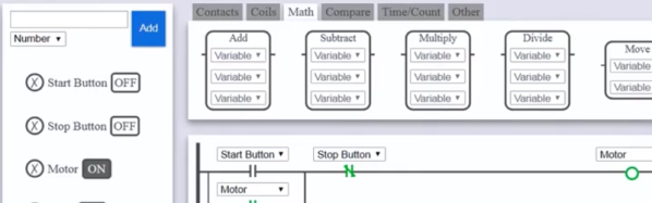
We all know what a short circuit is, but [Clement Zheng] and [Manasvi Lalwani] want to introduce you to the shirt circuit. Their goal is to help children, teachers and parents explore and learn electronics. The vehicle is a shirt with a breadboard-like pattern of conductors attaching snaps. Circuit elements reside in stiff felt boxes with matching snaps. You can see it all in action in the video below.
We imagine you could cut the felt pieces out by hand with the included patterns. However, they used a laser cutter to produce the “breadboard” and the component containers. Conductive thread is a must, of course, as are some other craft supplies like glue and regular thread.
A few years ago, there was a stir about a new fundamental component called a memristor. That wasn’t the first time a new component type was theorized though. In 1948 [Bernard Tellegen] postulated the gyrator. While you can’t buy one as a component, you can build one using other components. In fact, they are very necessary for some types of design. Put simply, a gyrator is a two-terminal device that inverts the current-voltage characteristic of an electrical component. Therefore, you can use a gyrator to convert a capacitor into an inductor or vice versa.
Keep in mind, the conversion is simply the electrical properties. Normally, current leads voltage in a capacitor and lags it in an inductor, and that’s what a gyrator changes. If you use a gyrator and a capacitor to make a virtual inductor, that inductor won’t magnetically couple to another inductor, real or simulated. There’s no magnetic field to do so. You also don’t get big voltage spikes caused by back EMF, which depending on your application could be a plus or a minus. But if you need an ungainly inductor in a circuit for its phase response, a gyrator may be just the ticket.
Every time we look at the little short Z axis of our CNC mill, we think about converting a drill press to a mill. In theory, it seems like it ought to be easy, but we never quite get around to it. [AvE] did get around to it and made his usual entertaining video about it that you can see below. If you haven’t seen any of [AvE’s] videos before, be warned: there is a little colorful language in a spot or two.
This isn’t a CNC mill, by the way, although we suspect you could convert it. Essentially, he adds a spindle and an XY table to a Ryobi drill press. It sounds simple, but getting everything to work did take a few tricks, including a blow torch.
Actually, turns out the blow torch didn’t really do it, but we won’t spoil the final resolution to the problem. Once it was resolved, though, he did manage to do some actual milling, accompanied by some music we wouldn’t associate with [AvE].
Although billed as a “poor man’s” build, the XY table alone was about $200. So add in the cost of the drill press, the spindle, and the mill and this is still a fair chunk of cash. We’d love to see it compared to a Harbor Freight milling vise. We suspect the Harbor Freight vise might not be as good, but is the difference worth the $130 difference in price?
We’ve seen this kind of conversion done before without the colorful language. If you do this conversion and want some practice, why not build a magnetic carabiner?
If you want to convert one voltage to another, what do you do? Well, if you are talking DC voltages today, you’ll probably use a DC to DC converter. Really, these converters generate some sort of AC waveform and then use either an inductor or a transformer to boost or buck the voltage as desired. Then they’ll convert it back to DC. If you are talking AC voltages, you could just use a transformer. But think about this: a transformer has two sides. The primary makes an alternating magnetic field. Just like rotating a shaft with magnets on it could. The secondary converts that alternating magnetic field into electricity just like a generator does. In other words, a transformer is just a generator that takes an AC input instead of a rotating mechanical input.
That’s a bit of an oversimplification, but in the old days, a lot of mobile radios (and other devices) took this idea to its logical conclusion. A M-G (Motor Generator) set was little more than a motor connected to a generator. The motor might take, say, 12V DC and the output could be, for example 300V AC that would get rectified for the plate voltage in a tube radio.
The ESP32 is the successor to the wildly popular ESP8266. There seems to be no end to what the chips can do. However, despite all the wireless communication capabilities, the module doesn’t have a display. [G6EJD] wanted to connect an ILI9341 TFT display and he put the code and information on GitHub. You can also see a video of his work, below.
Since the display uses a serial interface, there isn’t much wiring required. The Adafruit GFX library does the heavy lifting, utilizing the SPI library for the actual communications. The first demo shown on the hardware can pull weather data decoded. If you want more details on the display’s operation, check out [G6EJD’s] YouTube channel and you’ll find other videos that go into more detail.
We’ve seen these displays married to an ESP8266 with an integrated PCB, too. There’s a choice of libraries, and perhaps we’ll see a similar range of choice for the ESP32.
There’s a new and very detailed video tutorial about the Raspberry Pi available from the Australian firm Core Electronics. There are 30 videos and 5 chapters in total. A few of the introduction videos are short, but the detail videos range from 3 to 16 minutes.
The instructor [Michael] starts out at the very beginning — loading NOOBS on the Pi — and then moves on to Python, shell scripting, and building GUI applications with TkInter. It also covers using Particle Pi for IoT applications that integrate with IFTTT.
We do realize that most people reading Hackaday have probably used a Raspberry Pi at least once or twice. However, we also know that we all get asked to recommend material for beginners, or — in some cases — we are using material to teach classes in schools or hackerspaces.
When [ik1xpv] sets out to build a software-defined radio (SDR), he doesn’t fool around. His Breadboard RF103 sports USB 3.0, and 16-bit A/D converter that can sample up to 105 Msps, and can receive from 0 to 1800 MHz. Not bad. Thanks to the USB 3.0 port, all the signal processing occurs in the PC without the limitations of feeding data through a common sound port. You can see the device in action in the video below.
The Cypress FX3 USB device is an ARM processor, but it is only streaming data, not processing it. You can find the slightly modified firmware, a driver for using PC software, and schematics and board layouts on GitHub.