Faking A Hollow State Device

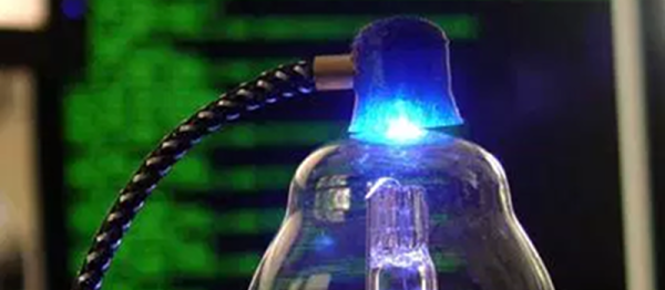
There’s been a resurgence of interest in vacuum tubes. Even if you do think audio sounds better through a tube, you have to admit the care and feeding of filaments and plate voltages isn’t trivial. [Ed Nisley] decided to sidestep all that and just build an objet d’art that looks like a tube.

A burned out halogen bulb stands in for the tube, and a ceramic base holds the bulb. It also conceals–what else–an Arduino. The Arduino drives a knock-off Neopixel LED hidden in a faux plate cap. The result is a glass envelope bathed in a cold blue and purple glow that changes under software control.

We’d really like to see this kind of tube inside some rebuilt piece of tube gear. Or maybe Korg should offer LED lighting options for their recent tube in a chip form factor. If you really want to be a top-tier tube hacker, you can always try your hand at repair.
Connect Four Robot Uses Raspberry Pi

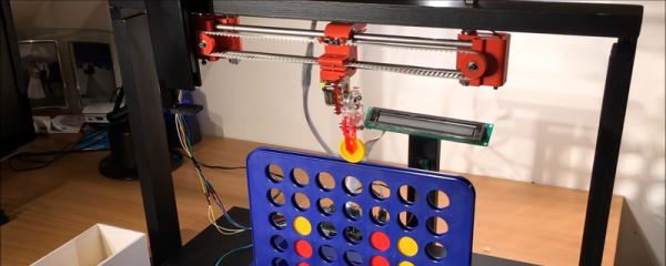
Most people play games for entertainment. Hackers build robots to play games for entertainment. That’s what [piandchips] did. He used a Raspberry Pi and a MeArm kit to build a Connect 4-playing robot. The robot–named 4-Bot–has to do two things: the first is it has to be able to manipulate the pieces. Secondly, it has to be able to see the board. The MeArm imbues 4-Bot with the manipulation ability, and a clever scanning system does the trick.

Continue reading “Connect Four Robot Uses Raspberry Pi” →

A Spicy Regenerative Reciever

We recently posted a three-part series about using LTSpice to simulate electronic circuits (one, two, three). You might have found yourself wondering: Can you really simulate practical designs with the program? This quick analysis of [QRP Gaijin’s] minimalist regenerative receiver says “yes”.

Continue reading “A Spicy Regenerative Reciever” →

Transforming Spice

Spice is a circuit simulator that you should have in your toolbox. While a simulator can’t tell you everything, it will often give you valuable insight into the way your circuit behaves, before you’ve even built it. In the first installment of this three-part series, I looked at LTSpice and did a quick video walkthrough of a DC circuit. In the second, I examined two other parts of Spice: parameter sweeps and AC circuits. In this final installment, I want to talk a bit more about real-world component performance and also look at modeling transformers.

Recap

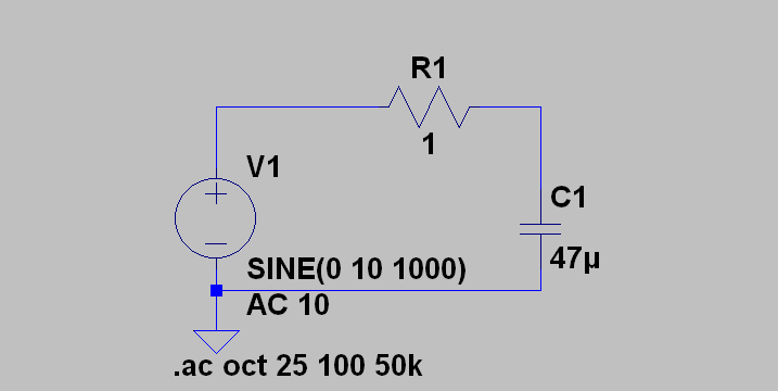
lowpasssLast time we looked at a low pass filter, but it wasn’t practical because the components were too perfect. Only in simulation do voltage sources and wires have zero resistance. There was no load resistance either, which is unlikely. Even an oscilloscope probe will load the circuit a little.

The resulting AC analysis showed a nice filter response that was flat to about 1 kHz and then started roll off as the frequency increased. Suppose the source had an 8 ohm series resistor. How does that change the circuit response?

Continue reading “Transforming Spice” →

Star Trek Pi

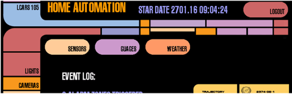
Every time we yell out, “OK Google… navigate to Velvet Melvin’s” we feel like a Star Trek character. After all, you’ve never seen Captain Kirk (or Picard) using a keyboard. If you get that same feeling, and you have a Raspberry Pi project in mind, you might enjoy the Raspberry Pi LCARS interface.

You can see the results in the video below. The interface uses PyGame, and you can customize it with different skins if you don’t want a Star Trek look.

Continue reading “Star Trek Pi” →

Spice Power

Spice is a circuit simulator that you should have in your toolbox. While a simulator can’t tell you everything, it will often give you valuable insight into the way your circuit behaves, before you’ve even built it. In the first installment of this three-part series, I looked at LTSpice and did a quick video walkthrough of a DC circuit. This time, I want to examine two other parts of Spice: parameter sweeps and AC circuits. So let’s get to it.

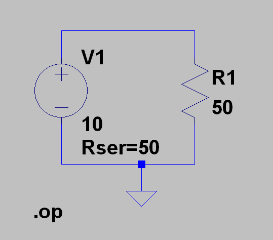
schem2In the first installment, I left you with a cliffhanger. Namely the question of maximum power transfer using this simple circuit. If you run the .op simulation you’ll get this result:

--- Operating Point ---
V(n001): 5 voltage
I(R1): 0.1 device_current
I(V1): -0.1 device_current

The power in R1 (voltage times current) is .5 W or 500 mW if you prefer. You probably know that the maximum power in a load occurs when the load resistor is the same as the source resistance. The Rser parameter sets the voltage source’s internal resistance. You could also have created a new resistor in series with V1 and set it explicitly.

Continue reading “Spice Power” →

PCB Laminator Is Its Own Project

One of the easiest ways to make PC boards at home is to use the toner transfer method. The idea is simple: print the artwork using a laser printer and then use a clothes iron to transfer the toner from the paper to a clean copper clad board. The toner is essentially plastic, so it will melt and stick to the board, and it will also resist etchant.

There are several things you can do to make things easier. The first is the choice of paper. However, the other highly variable part of the process is the clothes iron. You have to arrange for the right amount of heat and pressure. If you don’t do a lot of boards, you’ll probably have to make several passes at getting this right, scrubbing the reject boards with acetone and scouring pads to clean them again.

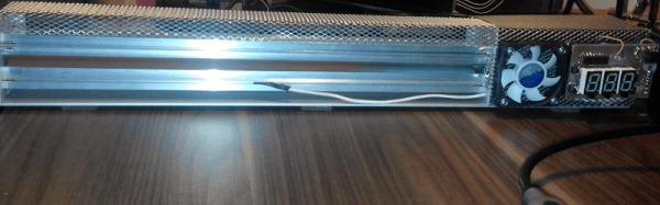
[Igor] had enough of the clothes iron and knew that other people have used lamination machines to get the toner off the paper and on the blank board. He started with a commercial laminator but hacked it for PID control of the temperature and made other improvements.

Continue reading “PCB Laminator Is Its Own Project” →