Casting a hand part 1

[Bil’s] Quest For A Lost Finger: Episode I

A little over a year ago I had a semi-gruesome accident; I stepped off of a ladder and I caught my wedding ring on a nail head. It literally stripped the finger off the bone. This was in spite of me being a safety-freak and having lived a whole second life doing emergency medicine and working in trauma centers and the like. I do have trauma center mentality which means, among other things, that I know you can’t wind the clock back.

hand9A few seconds make an incredible differences in people’s lives. Knowing that it couldn’t be undone, I stayed relaxed and in the end I have to say I had a good time that day as I worked my way through the system (I ended  up in a Philadelphia trauma center with a nearby hand specialist) as I was usually the funniest guy in the room. Truth be told they ask incredibly straight questions like”are you right handed?”  “Well I am NOW”.

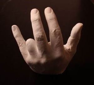
So now I could really use a bit of a body hack, having seen the X-Finger on Hackaday long before I knew that I would one day work with them, I was hoping that we could get one to work for me. In speaking with a couple of the mechanical engineers on the Hackaday staff we decided to get [James Hobson] and [Rich Bremer] involved and that the best way to do it was to get a casting of my injured hand out to them.


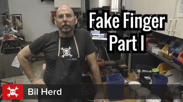
Continue reading “[Bil’s] Quest For A Lost Finger: Episode I”

Desoldering Surface Mount and Through Hole Components

SMT And Thru-Hole Desoldering

My introduction to electronic manufacturing was as a production technician at Pennsylvania Scale Company in Leola PA in the early 1980’s. I learned that to work on what I wanted to work on I had to get my assigned duties done by noon or thereabouts. The most important lesson I had learned as a TV repairman, other than not to chew on the high voltage cable, was to use your eyes first. I would take a box of bad PCB’s that were essentially 6502 based computers that could count and weigh, and first go through inspecting them; usually the contents were reduced 50% right off by doing this. Then it was a race to identify and fix the remaining units and to keep my pace up I had to do my own desoldering.

Desoldering with IR System

It worked like this; you could set units aside with instructions and the production people would at some point go through changing components etc. for you or you could desolder yourself. I was pretty good at hand de-soldering 28 and 40 pin chips using a venerable Soldapulit manual solder sucker (as they were known). But to really cook I would wait for a moment when the production de-soldering machine was available. There was one simple rule for using the desoldering station: clean it when done! Failure to do so would result in your access to the station being suspended and then you might also incur the “wrath of production” which was not limited to your lunch bag being found frozen solid or your chair soaked in defluxing chemicals.

Continue reading “SMT And Thru-Hole Desoldering”

Bil Herd: Computing With Analog

When I was young the first “computer” I ever owned was an analog computer built from a kit. It had a sloped plastic case which had three knobs with large numerical scales around them and a small center-null meter. To operate it I would dial in two numbers as indicated by the scales and then adjust the “answer” by rotating the third dial until the little meter centered. Underneath there was a small handful of components wired on a terminal strip including two or three transistors.

In thinking back about that relic from the early 1970’s there was a moment when I assumed they may have been using the transistors as logarithmic amplifiers meaning that it was able to multiply electronically. After a few minutes of thought I came to the conclusion that it was probably much simpler and was most likely a Wheatstone Bridge. That doesn’t mean it couldn’t multiply, it was probably the printed scales that were logarithmic, much like a slide rule.

Did someone just ask what a slide rule was? Let me explain further for anyone under 50. If you watch the video footage or movies about the Apollo Space Program you won’t see any anyone carrying a hand calculator, they didn’t exist yet. Yet the navigation guys in the first row of Mission Control known aptly as “the trench”, could quickly calculate a position or vector to within a couple of decimal places, and they did it using sliding piece of bamboo or aluminum with numbers printed on them.

Continue reading “Bil Herd: Computing With Analog”

Programmable Logic II – CPL

There is a wide assortment of cheap development (dev) boards for Complex Programmable Logic Devices (CPLD), the smaller cousin of the Field Programmable Logic Array (FPLA)

Using an inexpensive board and the development software that’s free to download from the major programmable companies such as Xilinx and Altera, the only additional thing needed is a programmer module. Cheap ones are available on Ebay but I am hoping that someone takes the time to teach an ARM/Arduino to step in as a programmer.

I have a small collection of dev boards including some Ebay specials and also designs I did a few years ago to choose from. For today I am grabbing a newer board that has not been fully checked out yet; an Altera Max V device. I have stuffed the CPLD, the clock oscillator, some LED’s and part of the onboard power supply along with the JTAG header needed to program the CPLD and that’s about it.


Herdware CPLD 5M570ZT
Herdware CPLD 5M570ZT dedicated PCB with SRAM.


CPLD Schematic
CPLD Schematic showing an Altera CPLD 5M570T144

Continue reading “Programmable Logic II – CPL”

Programmable Logic I – PLA/PAL


C64-B

Yeah I am still a little pissed that the competition is still around and we aren’t, and by “we” I mean Commodore Business Machines (CBM). It was Commodore that had the most popular home computer ever in the C64 (27 Million) and it was a team of MOS engineers after all, that had the idea to make a “micro” processor out of a 12 square inch PCB.

MOS Technologies logo and address
MOS Technology in King of Prussia/Norristown

Of course they did work at Motorola at the time and “Mot” did not want anything to do with a reduction of the profit margin on the pie-plate size processor. Of course MOS got sued by Motorola but that was an average Tuesday at MOS/CBM. I absolutely credit CBM with buying the MOS Technologies chip foundry, as together we could make our own processors, graphics chips, sound chips, memory controllers, and programmable logic.

With this arsenal at our call we didn’t have to make compromises the way other companies did such as conforming to the bus spec of an industrial standard 6845 or having to add extra logic when a custom extra pin would work. We could also make sprites.

6502 Design Team
6502 Design Team (EE Times 1975, archive.archaeology.org)

The compromise we did have to make when designing was cost, and I mean the kind of cost reduction where finding a way to save a dollar ($1USD) saved millions in the production run. I knocked $.90USD out of a transformer one day and I couldn’t focus the rest of the day due to elation.

Cost reduction is a harsh mistress however as you can’t just do it a little some of the time or only when you want to. The mental exercise of multiplying anything times a million was always there, it made it hard to buy lunch — I’d be blocking the lunch line while figuring the cost of a million tuna sandwiches FOB Tokyo Continue reading “Programmable Logic I – PLA/PAL”

Video: The Lowly Diode — Umpteen Functions With Only Two Pins

The lowly diode, a device with only two leads, can nonetheless do many things. Diodes can detect, rectify, suppress, emit light, detect light, change capacitance, emit microwaves and more. This wide range of use means diodes are included in almost every design and it’s well worth learning more about the inner workings of all kinds of diodes.

My introduction to diodes started like many of my generation with a homemade crystal radio set. My first diode was a piece of pencil graphite in contact with an old fashion safety razor with the joint of the two dissimilar materials — graphite and steel — creating the diode. In this configuration the diode is said to be “detecting” which is the act of turning a weak radio signal into a weak audio signal. At least in my home town of Marion Indiana, one radio station was stronger than the other so that I didn’t have to listen to two stations at once.

Germanium Glass Diode
The venerable 1N34A Germanium Signal Diode.

I eventually learned about “real” diodes and the 1N34A Germanium diode was my “goto” diode into my teens. Nowadays looking into a modern version of the 1N34A you can still see the semblance of the old “cat’s whisker” by looking carefully into the diode.

A quick and somewhat inaccurate semblance of the way a diode works can be demonstrated with marbles and jacks representing negative electrons and positive “holes”. Holes are basically an atom missing an electron due to the combination of elements, a process known as doping. Join me after the break for the explanation.

Demonstrating a PN Junction with marbles and Jacks.

Continue reading “Video: The Lowly Diode — Umpteen Functions With Only Two Pins”

Video: Getting Your Feet Wet With Programmable System On Chip

Ever since I received my PSOC 4 Pioneer kit from Cypress I have wanted to play with this little mixed-signal Programmable System-on-Chip (PSOC) developer board. I love developer boards, providing that they are priced in a way to entice me to not only open my wallet but also make time in a busy schedule. I think my kit was free after winning a swag bag from Adafruit that they themselves obtained at the Open Hardware Summit and gave away on their weekly streamcast. Ultimately it was the invitation to beta test datasheet.net which also was included in that pile of swag that led to my getting involved with Hackaday.

What is Programmable System On Chip?

So what is a PSOC 4? A quick summary is that it’s based on an ARM Cortex reduced instruction set processor (RISC) and is somewhat capable of supporting shields based on the Arduino footprint, and it also uses a bright red PCB that I have come to associate with a Sparkfun PCB. What doesn’t show is the fact that this programmable system on chip has programmable analog function blocks in addition to programmable digital logic blocks. There is also some supporting input/output circuitry such as a multicolored LED and a capacitive touch sensor directly on the PCB.

Pioneer 4 Development Kit
PSCO4 Development Board on Hackaday

This is an intriguing amount of programmability, so much so that Newark/Element 14 highlighted a “100 projects in 100 days” event on it.

Enter the IDE

Over the years I have had to create or install many Integrated Development Environments (IDE) that linked hardware to software. Knowing that you had to, and how to, implement an IDE was part of being an engineer. Nowadays with the Arduino type environment the user has an IDE pretty much as soon as they click on the executable which I find to be one of the best aspects of the genre. It was so quick in fact that I was able to get my teenaged son into writing his first program even before he remembered to do massive eye-rolls and make sounds of utter disdain. He did give up however, just shy of learning how to have the Arduino make sounds of disdain on his behalf.

PSCo4 Cypress Development Kit on Hackaday
Closeup of a Programmable System on Chip Development System

Continue reading “Video: Getting Your Feet Wet With Programmable System On Chip”