2025 One Hertz Challenge: 4-Function Frequency Counter

Frequency! It’s an important thing to measure, which is why [Jacques Pelletier] built a frequency counter some time ago. The four-function unit is humble, capable, and also an entry into our 2025 One Hertz Challenge!

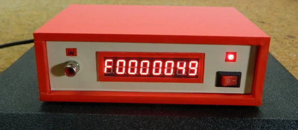
The build began “a long while ago when electronic parts were still available in local stores,” notes Jacques, dating the project somewhat. The manner of construction, too, is thoroughly old-school. The project case and the sweet red digits are both classic, but so is what’s inside. The counter is based around 4553 BCD counter chips and 4511 decoder ICs. Laced together, the logic both counts frequency in binary-coded decimal and then converts that into the right set of signals to drive the 7-segment displays. Sample time is either 1 Hz or 0.1 Hz, which is derived from an 8MHz oscillator. It can act as a frequency meter, period meter, chronometer, or a basic counter. The whole build is all raw logic chips, there are no microprocessors or microcontrollers involved.

It just goes to show, you can build plenty of useful things without relying on code and RAM and all that nonsense. You just need some CMOS chips and a bucket of smarts to get the job done!

2025 One-Hertz Challenge: ZX Spectrum Is Now A Z80 Frequency Counter

The ZX Spectrum is perhaps most fondly remembered as a home computer and a games machine. [Tito] has grabbed the faithful black plastic box and turned it into a frequency counter as an innovative entry to our 2025 One Hertz Challenge.

The code was prepared in assembly using ZASM—a Z80 online assembler. It works in quite a simple manner. The code runs for one second at a time, counting rising edges on the EAR port of the ZX Spectrum. Those edges are added up to determine the frequency in question, and the job is done. [Tito] has tested the code and found it’s capable of reading frequencies up to 20 KHz. Since it runs on a one second period, it’s thus eligible for entry by meeting the requirements of the One Hertz Challenge. Code is available on Github for the curious.

The ZX Spectrum has a clock speed of 3.5 MHz, meaning it’s not exactly the tool of choice if you’re reading faster signals. We’ve seen similar done before. In any case, this project was a great way to exercise assembly coding skills and to bust out some classic Speccy hardware—and that’s always a good time. If you’ve got your own retrocomputer hacks brewing up in the lab, don’t hesitate to let us know!

Upgrade Puts A Lot Of Zeroes On Kit-Built Frequency Counter

If there’s anything more viscerally pleasing than seeing an eight-digit instrument showing a measurement with all zeroes after the decimal point, we’re not sure what it could. Maybe rolling the odometer over to another 100,000 milestone?

Regardless, getting to such a desirable degree of accuracy isn’t always easy, especially when the instrument in question is a handheld frequency counter that was built from a kit 23 years ago. That’s the target of [Petteri Aimonen]’s accuracy upgrade, specifically by the addition of a custom frequency reference module. The instrument is an ELV FC-500, which for such an old design looks surprisingly modern. Its Achille’s heel in terms of accuracy is the plain crystal oscillator it uses as a frequency standard, which has no temperature compensation and thus drifts by about 0.2 ppm per degree.

For a mains-powered lab instrument, the obvious solution would be an oven-controlled crystal oscillator. Those are prohibitive in terms of space and power for a handheld instrument, so instead a VCTCXO — voltage-controlled, temperature-compensated crystal oscillator — was selected for better stability. Unfortunately, no such oscillators matching the original 4.096-MHz crystal spec could be found; luckily, a 16.384-MHz unit was available for less than €20. All that was required was a couple of flip-flops to divide the signal by four and a bit of a bodge to replace the original frequency standard. A trimmer allows for the initial calibration — the “VC” part — and the tiny PCB tucks inside the case near the battery compartment.

We enjoyed the simplicity of this upgrade — almost as much as we enjoyed seeing all those zeroes. When you know, you know.

Frequency Counter Restoration Impeded By Kittens

We think of digital displays as something you see on relatively modern gear. But some old gear had things like nixies or numitrons to get cool-looking retro digital displays. The HP 521A frequency counter, though, uses four columns of ten discrete neon bulbs to make a decidedly low-tech but effective digital display. [Usagi Electric] has been restoring one of these for some time, but there was a gap between the second and third videos as his workshop became a kitten nursery. You can see the last video below.

In previous videos, he had most of the device working, but there were still some odd behavior. This video shows the final steps to success. One thing that was interesting  is that since each of the four columns are identical, it was possible to compare readings from one decade to another.

However, in the end, it turned out that the neon bulbs were highly corroded, and replacing all the neon bulbs made things work better. However, the self-check that should read the 60 Hz line frequency was reading 72 Hz, so it needed a realignment. But that was relatively easy with a pot accessible from the back panel. If you want to see more details about the repair, be sure to check out the earlier videos.

We love this old gear and how clever designers did so much with what we consider so little. We hate to encourage your potential addiction, but we’ve given advice on how to acquire old gear before. If you want to see what was possible before WS2812 panels, you could build this neon bulb contraption.

Continue reading “Frequency Counter Restoration Impeded By Kittens”

Old-school frequency counter

Edge-Mounted Meters Give This Retro Frequency Counter Six Decades Of Display

With regard to retro test gear, one’s thoughts tend to those Nixie-adorned instruments of yore, or the boat-anchor oscilloscopes that came with their own carts simply because there was no other way to move the things. But there were other looks for test gear back in the day, as this frequency counter with a readout using moving-coil meters shows.

We have to admit to never seeing anything like [Charles Ouweland]’s Van Der Heem 9908 electronic counter before. The Netherlands-based company, which was later acquired by Philips, built this six-digit, 1-MHz counter sometime in the 1950s. The display uses six separate edge-mounted panel meters numbered 0 through 9 to show the frequency of the incoming signal. The video below has a demo of what the instrument can do; we don’t know if it was restored at some point, but it still works and it’s actually pretty accurate. Later in the video, he gives a tour of the insides, which is the real treat — the case opens like a briefcase and contains over 20 separate PCBs with a bunch of germanium transistors, all stitched together with point-to-point wiring.

We appreciate the look inside this unique piece of test equipment history. It almost seems like something that would have been on the bench while this Apollo-era IO tester was being prototyped.

Continue reading “Edge-Mounted Meters Give This Retro Frequency Counter Six Decades Of Display”

NTP, Rust, And Arduino Make A Phenomenal Frequency Counter

Making a microcontroller perform as a frequency counter is a relatively straightforward task involving the measurement of the time period during which a number of pulses are counted. The maximum frequency is however limited to a fraction of the microcontroller’s clock speed and the accuracy of the resulting instrument depends on that of the clock crystal so it will hardly result in the best of frequency counters. It’s something [FrankBuss] has approached with an Arduino-based counter that offloads the timing question to a host PC, and thus claims atomic accuracy due to its clock being tied to a master source via NTP. The Rust code PC-side provides continuous readings whose accuracy increases the longer it is left counting the source. The example shown reaches 20 parts per billion after several hours reading a 1 MHz source.

It’s clear that this is hardly the most convenient of frequency counters, however we can see that it could find a use for anyone intent on monitoring the long-term stability of a source, and could even be used with some kind of feedback to discipline an RF source against the NTP clock with the use of an appropriate prescaler. Its true calling might come though not in measurement but in calibration of another instrument which can be adjusted to match its reading once it has settled down. There’s surely no cheaper way to satisfy your inner frequency standard nut.

Easy Frequency Counter Looks Good, Reads To 6.5 MHz

We were struck by how attractive [mircemk’s] Arduino-based frequency counter looks. It also is a reasonably simple build. It can count up to 6.5 MHz which isn’t that much, but there’s a lot you can do even with that limitation.

The LED display is decidedly retro. Inside a very modern Arduino Nano does most of the work. There is a simple shaping circuit to improve the response to irregular-shaped input waveforms. We’d have probably used a single op-amp as a zero-crossing detector. Admittedly, that’s a bit more complex, but not much more and it should give better results.

Continue reading “Easy Frequency Counter Looks Good, Reads To 6.5 MHz”