Hackaday Prize 2023: Eye Tracking On A Budget

There is a lot to be learned from the experience of building something functional, and even better if doing so doesn’t break the bank. [Sergej Stoetzer]’s 20€ DIY-Eyetracker aims to be an educational process that covers everything from hardware to functional software in an accessible way.

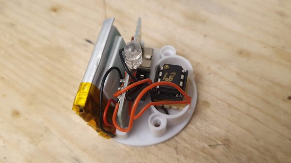
Hardware based on an economical USB endoscope, and can be used as-is or repackaged with IR illumination.

The eye tracker is based on an economical USB endoscope, which is a small camera optimized for up-close applications. By attaching the camera to a pair of common safety glasses so that it looks at one’s eye, some OpenCV and Python code can do simple tracking and interfacing with other projects.

Basic eye tracking — like determining whether a user is looking up, down, left, or right — can be all that’s needed depending on one’s application. That means that it’s possible to get something working with very little hardware and some easy-to-use OpenCV functions.

Even better performance can be had by adding IR illumination and repackaging the camera into a 3D printed enclosure. The pupil of the eye is an aperture in the iris that appears as a black circle, and that’s even more true under IR illumination which is invisible to the naked eye. If you’re curious about what’s inside those USB endoscope cameras and how to remove their IR filter, there are some good pictures of that process in this project.

The ability to get something prototyped quickly and working well enough to learn new things is a valuable skill, and that’s why re-engineering Education is one of the challenges in the 2023 Hackaday Prize.

FET: Fun Endeavors Together

Last time, we’ve looked over FET basics, details, nuances and caveats. Basics aren’t all there is to FETs, however – let’s go through real-world uses, in all their wonderful variety! I want to show you a bunch of cool circuits where a friendly FET, specifically a MOSFET, can help you – and, along the way, I’d also like to introduce you to a few FETs that I feel like you all could have a good long-term friendship with. If you don’t already know them, that is!

Driving Relays

Perhaps, that’s the single most popular use for an NPN transistor – driving coils, like relays or solenoids. We are quite used to driving relays with BJTs, typically an NPN – but it doesn’t have to be a BJT, FETs often will do the job just as fine! Here’s an N-FET, used in the exact same configuration as a typical BJT is, except instead of a base current limiting resistor, we have a gate-source resistor – you can’t quite solder the BJT out and solder the FET in after you have designed the board, but it’s a pretty seamless replacement otherwise. The freewheel (back EMF protection) diode is still needed for when you switch the relay and the coil produces wacky voltages in protest, but hey, can’t have every single aspect be superior.

The reason you can drive it the same way is quite simple: in the usual NPN circuit, the relay is driven by a 3.3 V or a 5 V logic level GPIO, and for small signal FETs, that is well within Vgs. However, if your MCU has 1.8 V GPIOs and your FET’s Vgs doesn’t quite cut it, an NPN transistor is a more advantageous solution, since that one will work as long as you can source the whatever little current and the measly 0.7 V needed.

Continue reading “FET: Fun Endeavors Together”

Op Amp Challenge: An Ultra-Cheap PH Sensor Amplifier

It’s rare in 2023 for an instrument to be entirely analog, instead it’s more normal for a front-end to feed the analog-to-digital converter (ADC) in a microcontroller. Typically the front-end will do the job of transforming whatever the output range of the sensor is, and present it to the microcontroller in whatever range it accepts. [David] had exactly this problem with a pH sensor, and rather than buy an expensive module to do the job he designed his own.

The sensor in question produces a relatively tiny voltage of -0.414 to +0.414 volts, and requires a very high input impedance. A FET input op-amp is selected, with the ground of the sensor shifted upwards into the positive range by a voltage divider. This then feeds a second op-amp that amplifies the resulting DC voltage for the microcontroller input.

This circuit is an especially simple op-amp application, and is a typical one for a sensor interface where a DC voltage needs to be brought into range of a microcontroller. If you’re not used to op-amp circuits then take a look, this type of analogue circuit is not difficult and might just save your butt some time.

Want to know more about simple op-amp circuits? Have we got the video for you!

Getting Ready For Act 2 Of The Great American Eclipse

It seems like only yesterday that the “Great American Eclipse” swept from coast to coast, and for those who were lucky enough to watch it from along the path of totality, it was a true life experience. No natural phenomenon can compete with the beauty of a total solar eclipse, and if there’s one thing I heard more than anything else in those golden moments after the Sun returned from behind the Moon, it was, “When’s the next one?” Everyone wanted to do it again, and for good reason.

Back in 2017, that question was kind of rhetorical; everyone knew the next eclipse to cross the United States was a mere seven years off. For me personally, the passage of time has not dampened my enthusiasm for eclipses one bit, and I suspect the feeling is mutual among the many people who gazed in wonder and childlike glee at the celestial proceedings of 2017. But except for the very lucky who live within the path of totality, mounting an expedition that optimizes the viewing experience takes preparation. Now that we’re a little less than a year away for the next one, it’s time to get geared up and make plans for the 2024 eclipse.

Where and When?

The 2017 eclipse’s “Great American Eclipse” moniker was well earned, as the continental United States was the sole beneficiary of the view. This time around, the US isn’t the only country along the path; Mexico and Canada will also get in on the fun. In fact, Mexico may well be the best place to watch the eclipse from, but more on that later. Continue reading “Getting Ready For Act 2 Of The Great American Eclipse”

An IN-12B Nixie tube on a compact driver PCB

Modern Components Enable Cheap And Compact Nixie Driver Circuit

Nixie tubes can add some retro flair to any project, but they can also complicate your electronics quite a bit: after all, you need to generate a voltage high enough to ignite the tube and then switch that between ten separate display segments. Traditionalists may want to stick with chunky mains transformers and those unobtainium 74141 segment drivers, but modern components allow you to make things much more compact, not to mention way cheaper. [CNLohr] took this to an extreme, and used clever design tricks and his sharp online shopping skills to make an exceptionally compact Nixie driver circuit that costs less than $2.50.

That price doesn’t include the tubes themselves, but [CNLohr] nevertheless bought the cheapest Nixies he could find: a pair of IN-12B tubes that set him back just $20. He decided to generate the necessary 180 volts through a forward converter built around a $0.30 transformer and a three-cent MOSFET, controlled by software running on a CH32V003. This is one of those ultra-cheap microcontrollers that manage to squeeze a 48 MHz RISC-V core plus a bunch of peripherals into a tiny QFN package costing just 12 cents.

The existing toolchain to program these micros left a lot to be desired, so [CNLohr] wrote his own, called
ch32v003fun. He used this to implement all the control loops for the forward converter as well as PWM control of the display segments – a feature that adds a beautifully smooth turn-on and turn-off effect to the Nixie tubes. There’s still plenty of CPU capacity left to implement other features, although [CNLohr] isn’t sure what to put there yet. Turning the tubes into a clock would be an obvious choice, but the basic system is flexible enough to implement almost anything requiring a numeric display.

The compactness of this circuit is impressive, especially if you compare it to earlier solutions. There’s plenty of fun to be had with cheap-yet-powerful micros like the ch32v003, provided you can find them.

Continue reading “Modern Components Enable Cheap And Compact Nixie Driver Circuit”

Machine Vision Automates Trainspotting With Unique Full-Length Portraits

As hobbies go, trainspotting is just as valid a choice as any — we don’t judge. But it does present certain logistical challenges, such as having to be in visual range of a train to be able to spot it. There’s also the fact that trains are very large objects, and they tend to move very fast. What’s a railfan to do?

If you’re also technically minded, you might try building an automatic trainspotting bot like [jo-m] has. It looks like the hardware end of “Trainbot” is pretty simple since it has been tested on both x86 and Raspberry Pi, and supports both video4linux and Pi cam. The magic is in the software, which is able to detect a train entering the frame, record images, and then stitch them together into one long image. The whole thing is coded in Go and has some interesting bits, like a custom image patch mapping package.

Trainbot gives an unusual view of a train, one that most of us accustomed to watching a train pass at a crossing have never seen. By stitching small chunks of the train as it passes, Trainbot is able to show the entire train in a single image, which would be impossible to do except for being very, very far away from the track. [jo-m] also built a web interface for Trainbot where you can check out the comings and goings yourself. Each passing train’s image is accompanied by data like its velocity and acceleration, length of the train, and time of passage. There’s also a GIF of the original source video, which is pretty cool.

Here in the States, we don’t have a lot of passenger trains to spot, but we do have some really long freight trains. It’d be interesting to see how this works with a train that’s over a mile long; that would be quite an image. Looks like someone at least has the hardware in place to give it a try.

Recreating A Non-Standard USB Cable

USB is a well-defined standard for which there are a reasonable array of connectors for product designers to use in whatever their application is. Which of course means that so many manufacturers have resorted to using proprietary connectors, probably to ensure that replacements are suitably overpriced. [Teaching Tech] had this problem with a fancy in-car video device, but rather than admit defeat with a missing cable, he decided to create his own replacement from scratch.

The plug in use was a multi-way round design probably chosen to match the harshness of the automotive environment. The first solution was to hook up a USB cable to a set of loose pins, but after a search to find the perfect-fitting set of pins a 3D printed housing was designed to replace the shell of the original. There’s an ouch moment in the video below the break as he receives a hot glue burn while assembling the final cable, but the result is a working and easy to use cable that allows access to all the device functions. Something to remember, next time you have a proprietary cable that’s gone missing.

Continue reading “Recreating A Non-Standard USB Cable”