What better way to learn to use Git than a gamified interface that visualizes every change? That’s the idea behind Oh My Git! which aims to teach players all about the popular version control system that underpins so many modern software projects.

Sometimes the downside to a tool being so ubiquitous is that it tends to be taken for granted that everyone already knows how to use it, and those starting entirely from scratch can be left unsure where to begin. That’s what creators [bleeptrack] and [blinry] had in mind with Oh My Git! which is freely available for Linux, Windows, and macOS.
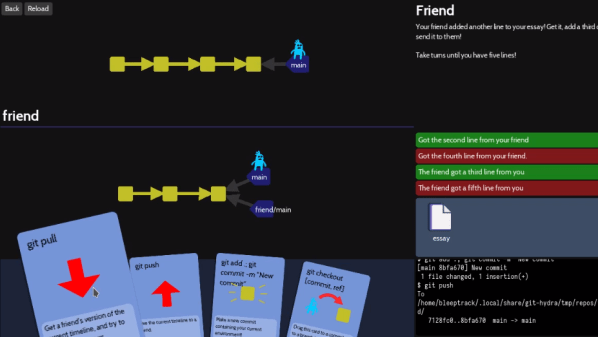
The idea is to use a fun playing-card interface to not only teach players the different features, but also to build intuitive familiarity for operations like merging and rebasing by visualizing in real-time the changes a player’s actions make.
The game is made with beginners in mind, with the first two (short) levels establishing that managing multiple versions of a file can quickly become unwieldy without help. Enter git — which the game explains is essentially a time machine — and it’s off to the races.
It might be aimed at beginners, but more advanced users can learn a helpful trick or two. The game isn’t some weird pseudo-git simulator, either. The back end uses real git repositories, with a real shell and git interface behind it all. Prefer to type commands in directly instead of using the playing card interface? Go right ahead!
Oh My Git! uses the free and open-source Godot game engine (not to be confused with the Godot machine, a chaos-based random number generator.)