If you were a kid anywhere in the last 30 years, it was nearly impossible to avoid at least some exposure to the Pokemon franchise. Whether that’s through games like Red and Blue to Scarlet and Violet, the brief summer everyone played Pokemon Go, or to other media such as the trading card game or anime, it seems to have transcended generations and cultures fairly thoroughly. And, if you’ve consumed all there is of official Pokemon video gaming, you may be surprised to know there are a number of slightly modified games floating around out there that can be translated onto game carts just like their official counterparts.
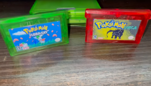
[imablisy] has played a lot of these ROM hack games but always within something like a virtual console or emulator, so he wanted something physical which would work on original hardware of the era. For this he’s making physical copies of Flora Sky and Vega, which are based on Pokemon Emerald and Fire Red originally for the Game Boy Advance. To get the cart he found a bunch of Mother 3 cartridges to use as the donor. From there he backed up his Emerald and Fire Red cartridges, modified the ROMs with the modifications, and then sent those new ROMs to overwrite the data on the Mother 3 cartridges.
A playable cartridge is only half of the build, though. He wants these to look and feel like real Pokemon games, so he added a color-appropriate translucent case and also printed custom holographic labels for each. It might seem straightforward, but from the style of [imablisy]’s video it’s clear he is very familiar with processes like these, from the artwork all the way to the hardware and software side. We’re also pleased no classic hardware was damaged during this build, much like this version of Doom on an NES cart which used a common game for the donor to upset the least number of collectors.
Continue reading “Pokemon ROM Hacks Brought To The Real World”
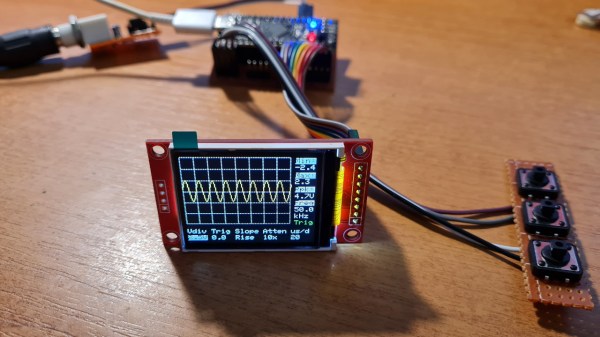
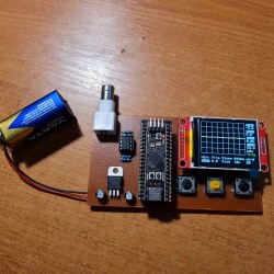 It’s hard to overshadow just how easy this scope is to build, use, and hack on. You really don’t need much in the way of parts, a protoboard will do, though you can also etch or order