Roller coasters are not only great fun to ride, they’re also fascinating pieces of engineering. Building your own full-size coaster is sadly beyond most people’s means, so the average enthusiast will have to settle for simulation or modelling of their own designs. [Jon Mendenhall] is one of those who specialize in building model roller coasters and simulating their motion in intricate detail. His latest project is a scale model of VelociCoaster, a Jurassic Park-themed ride in Universal’s Islands of Adventure, that simulates the coaster’s ride without using any moving parts.
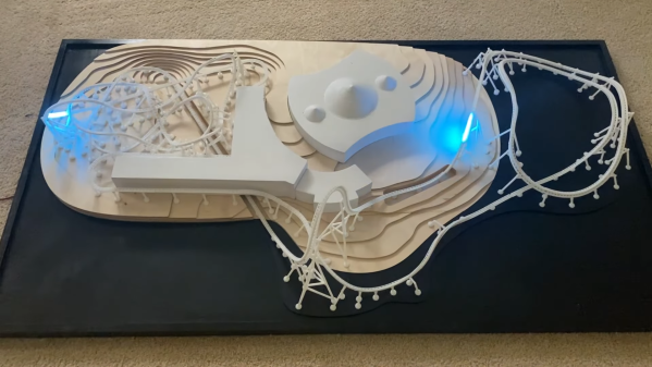
[Jon] achieves this by re-creating the trains’ motion using LED strips. A total of 3000 LEDs are spread along more than nine meters of track and make a mesmerizing light show of several trains whizzing along the track, accelerating and slowing down exactly like the real thing.
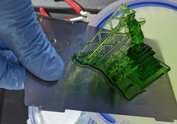
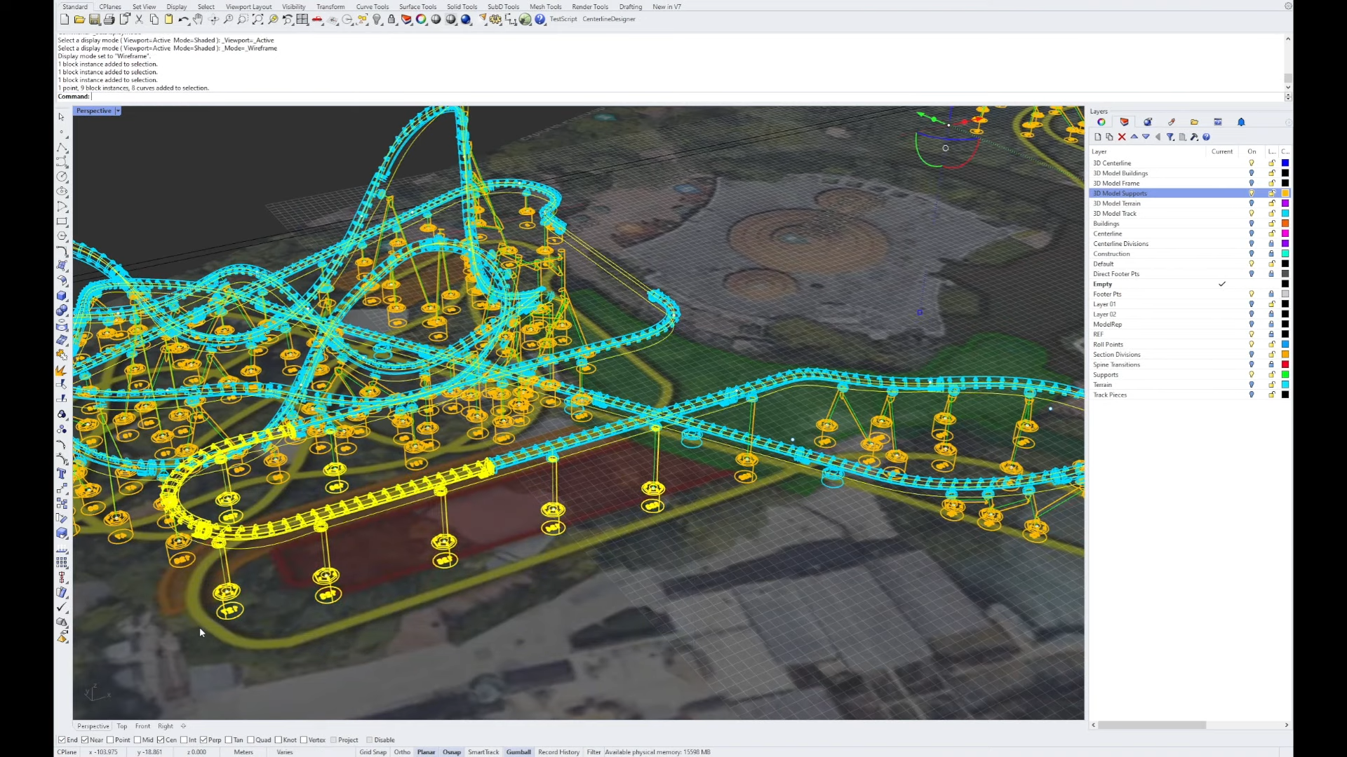 In his video, [Jon] explains the process of generating an accurate 3D model of the track starting from nothing more than an overhead view of the park as well as photos taken from various angles. The surrounding terrain and buildings are also included in his 3D model, as are the 128 supports that hold the track in place. The terrain and building were made from plywood and foam using a CNC machine, while the track and supports were 3D printed.
A Teensy microcontroller runs the whole show, with the LED strips split into five separate sections to allow a high enough frame rate for smooth animations. An infrared remote is used to start and stop the ride, as well as to adjust the speed; the model supports running the trains at a physically accurate speed, but because this looks rather dull, the regular setting is about three times as fast.
Looking for more roller coaster models? [Jon] made a similarly impressive model with a powered train before, and we’ve seen several models that actually coast along their tracks.
Continue reading “How To Make A Model Roller Coaster Without Any Moving Parts”