Many years of using televisions, monitors, and projectors have conditioned us into treating them as simple peripherals whose cables carry only video. A VGA cable may have an i2c interface for monitor detection, but otherwise it presents little security risk. An HDMI interface on the other hand can carry an increasing number of far more capable ports, meaning that it has made the leap from merely a signal cable to being a connector stuffed with interesting attack vectors for a miscreant. Is it time for an HDMI firewall? [King Kévin] thinks so, because he’s made one.
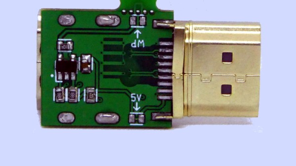
It’s a surprisingly simple device, because the non-signal capabilities of HDMI rely on a set of conductors which are simply not connected. This of course also disconnects the on-board EEPROM in the device being connected, so there’s an EEPROM on the firewall board to replace it which must be programmed with the information for the device in question.
The premise of HDMI as an attack surface is a valid one, and we’re sure there will be attacks that can be performed on vulnerable displays which could potentially in turn do naughty things to anything which connects to them. The main value for most readers here probably lies though in the introduction it gives to some of what goes into an HDMI interface, and in accessing the i2c interface therein.
It comes as a surprise to realise that HDMI is nearing 20 years old, so it’s hardly surprising that its hacking has quite a history.