When we first developed telescopes, we started using them on the ground. Humanity was yet to master powered flight, you see, to say nothing of going beyond into space. As technology developed, we realized that putting a telescope up on a satellite might be useful, since it would get rid of all that horrible distortion from that pesky old atmosphere. We also developed radio telescopes, when we realized there were electromagnetic signals beyond visible light that were of great interest to us.
Now, NASA’s dreaming even bigger. What if it could build a big radio telescope up on the Moon?
Things may not have gone as planned last week for the flying cellphone on Mars, but just because Ingenuity‘s flying career is over doesn’t mean there’s no more work to do. NASA announced this week that it’s going to try a series of “wiggle” maneuvers on Ingenuity‘s rotors, in an attempt to get a better look at the damage to the blade tips and possibly get some clues as to what went wrong. The conjecture at the moment seems to be that a large area of relatively featureless terrain confused the navigation system, which uses down-facing cameras to track terrain features. If the navigation program couldn’t get a bead on exactly how far above the ground it was, it’s possible the copter came in too hard and caused the rotor tips to dig into the regolith. There seems to be some photographic suggestion of that, with what looks like divots in the ground about where you’d expect the rotor tips to dig in, and even scraps of material that look out of place and seem to be about the same color as the rotor blades. All this remains to be seen, of course, and we’re sure that NASA and JPL are poring over all available data to piece together what happened. As much as we hate to say goodbye to Ingenuity, we eagerly await the post-mortem.
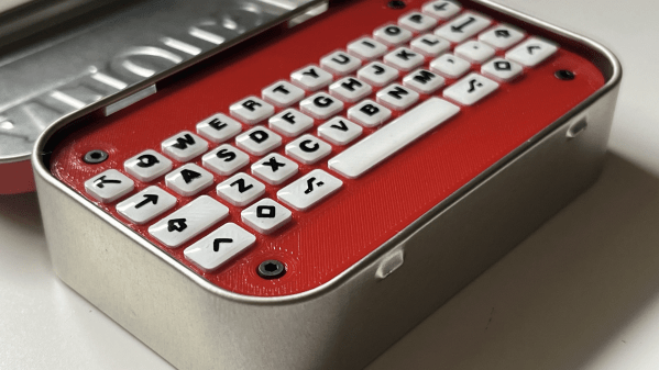
Well, here’s a fresh idea! [flurpyflurples] is back from hiatus with the Mintboard, a 40% that fits inside of an Altoids tin. Who could ask for more than a rugged little Bluetooth keyboard with a built-in cover that fits in your pocket?
This build started with meticulously measuring the tin to figure out what kind of switches could be used. At first, this was going to be a 60% keyboard, but after a lot of design decisions and switch comparisons, [flurpyflurples] settled on a certain micro switch spaced at 7.3mm for a 40% layout. Then it was time to design a PCB.
Although [flurpyflurples] tends to use Arduino Pro Micros in their builds, they went with the Nice! Nano this time for the Bluetooth capabilities. This means that they had to program it with ZMK instead of QMK, but found that QMK knowledge transfers rather nicely.
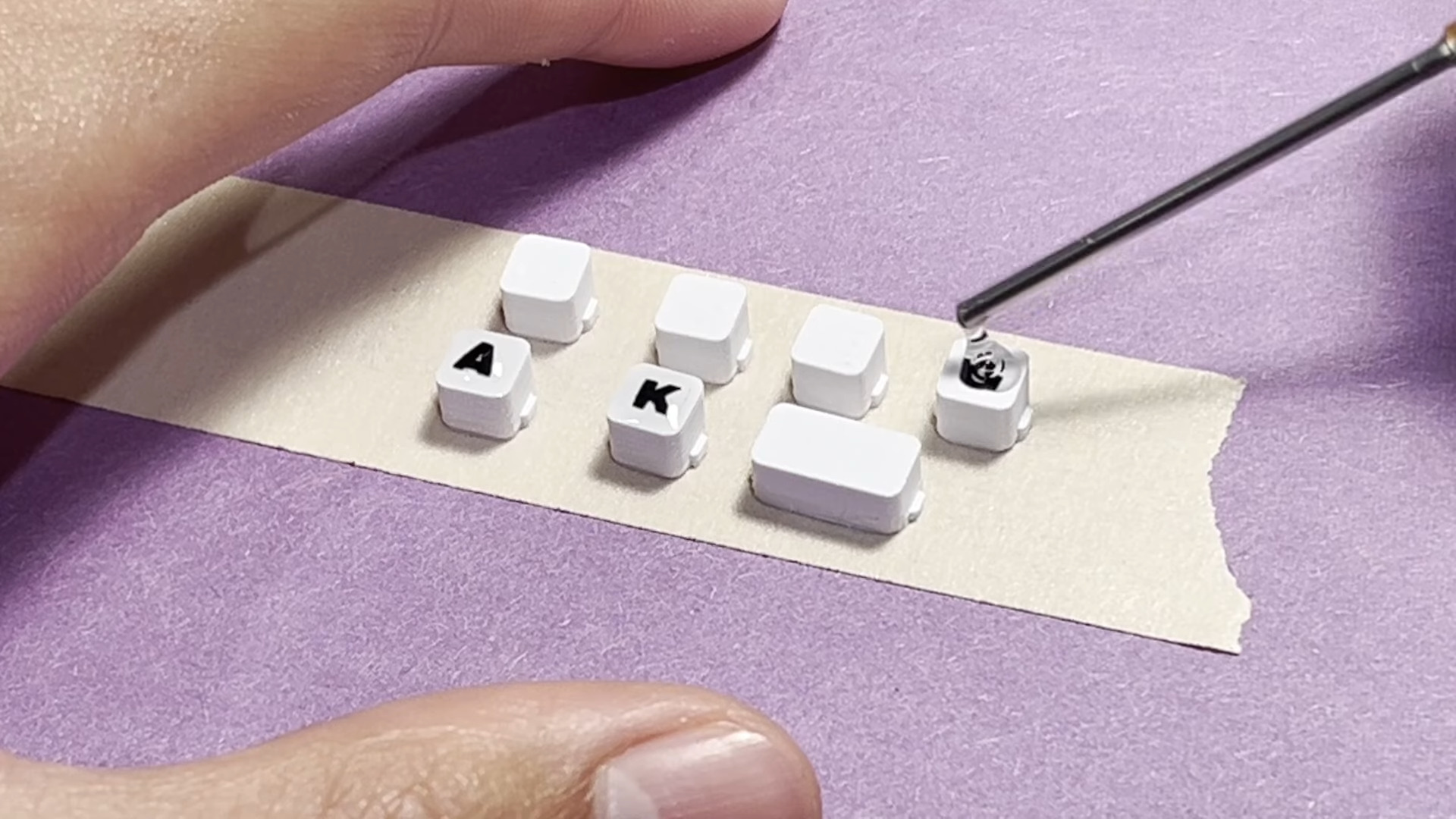
Let’s talk about those lovely legends. The keycaps are 3D printed of course, and the legends were cut out on a Cricut machine. The best part is that sealant — [flurpyflurples] used a few drops of UV nail polish top coat and cured it with light.
We think this looks and sounds fantastic, and would really like to know how to get such clean cutouts. According to [flurpyflurples] and the end of the build/demo video you’ll find below the break, the action is a lot like a Blackberry keyboard.
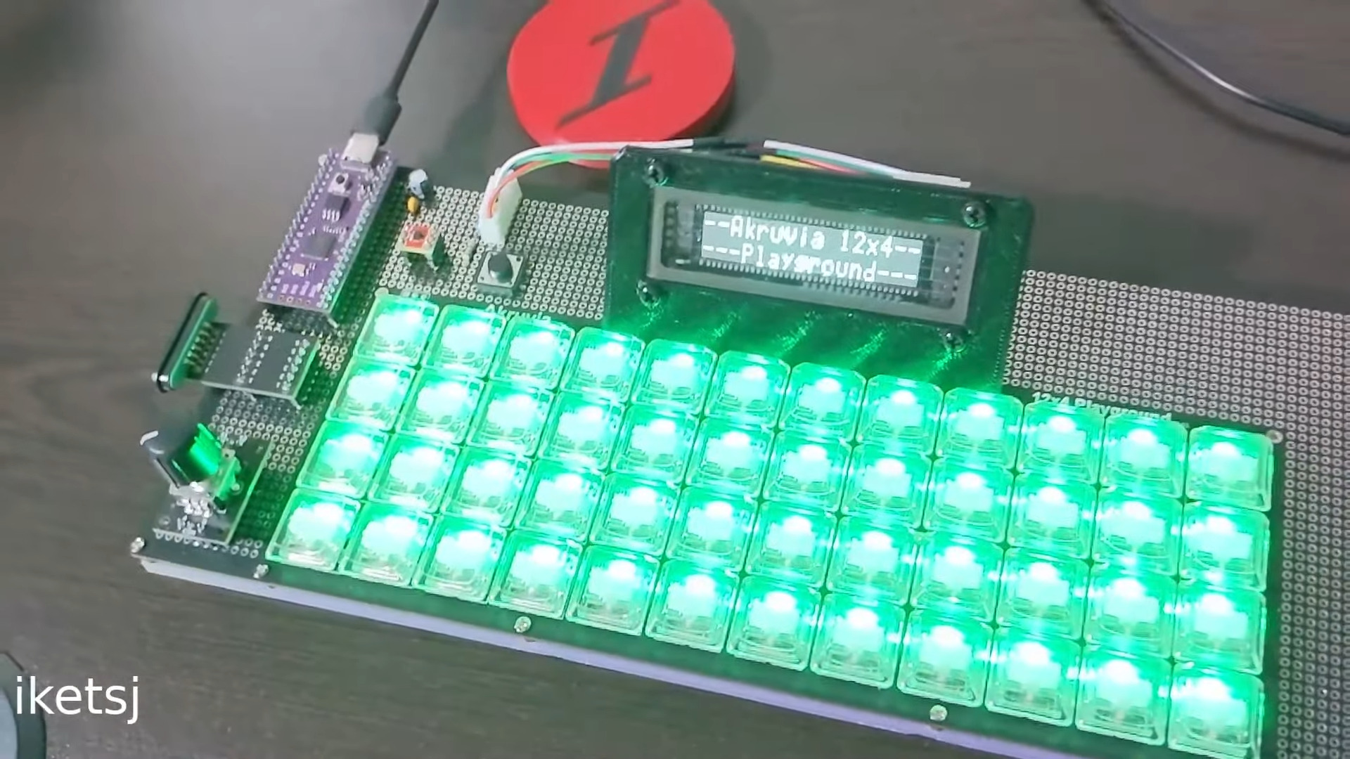
Have you ever wished you had more control over what goes into a kit keyboard build? Like, a whole lot more control? Well, that’s the idea behind the Akruvia 12×4 Playground by [iketsj].
This is a 48-key ortholinear keyboard, but other than that, it’s a complete blank slate. The kit includes the PCB, diodes, RGB LEDs, and Kailh Choc V1 hot swap sockets, which is really the only choice you don’t have in the matter.
All the rest is up to you, thanks to a generous prototyping area that wraps around three sides of the keys. Bring your own microcontroller and anything else that sounds useful, like displays, rotary encoders, gesture sensors, pointing devices, you name it.
You could even magnetically link a macro pad to one side, as [iketsj] teases in the intro video. [iketsj] has made the kit available through links on their website, and you’ll find a product guide there as well.
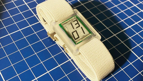
[Augusto Marinucci] liked the classic Cartier Tank series of dress watches aesthetic, but wanted something a bit more techy, with a decent runtime on a single battery. E-Ink displays are often used in such applications, but finding one to fit a custom case design, is a tall order. When ordering one off the shelf is not easy, the solution is to make one from scratch.
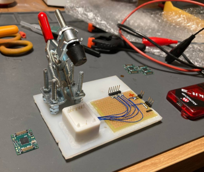
Building a programming jig is a great idea for small-scale production
The article doesn’t have much information on the E-Ink side of things, which is a bit of a shame. But from what we can glean, the segment shapes — in this case, based on the famous Apollo DSKY — are formed in the top copper of a four-layer PCB, using filled and capped vias to connect invisibly from below.
A donor E-Ink display is cut to size with scissors (we don’t know much more than this!) and glued in place around the edge to make the common electrode connection. The display PCB attaches to the control PCB, at the rear using low-profile board-to-board connectors. This board hosts a PIC16 micro, as well as an RV-3028-C7 RTC which keeps time whilst consuming a paltry 45 nA.
Five volts are provided via a MAX1722 low-power boost converter which is fed power from the CR1616 cell via a couple of logic-controllable load switches. With a low-power design such as this, it’s critical to get this correct. Any mistakes here can easily result in a very low runtime. It is easy to over-stress small button cells and kill them prematurely.
The case looks like it’s printed in a translucent resin, with the PCB stack sealed inside with a UV-cured resin pour. It’s not immediately obvious if the rear panel can be removed to access the battery and programming port. There are what appear to be screw holes, so maybe that’s possible, or maybe they’re the rear side of the PCB mounting posts. Who can tell?
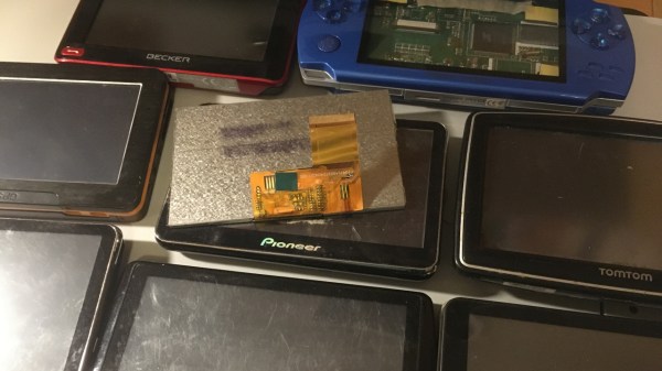
You might have seen old display panels, from 3″ to 10″, with 40-pin FFC connectors where every pin seems to be used for some data signal. We call these displays parallel RGB, or TTL RGB, or DPI, and you can find them in higher-power MCU, Raspberry Pi, and other Linux SBC projects. You deserve to know what to do with those – let’s take a look.
The idea is simple – this interface requires you to constantly send a stream of pixels to the display, and you need to send those pixels through a parallel bus. You can send up to 8 bits per color channel per pixel, which makes for 24 bits, and the 24-bit mode is indeed the standard, but in practice, many parallel RGB implementations don’t bother with more than 5-6 bits of color – two common kinds of parallel RGB links are RGB565 and RGB666. The parallel RGB interface is a very straightforward approach to sending pixels to your display, and in many cases, you can also convert parallel RGB to LVDS or VGA interfaces relatively easily!
If you’re new to it, the easiest way you can drive a parallel RGB display is from a Raspberry Pi, where the parallel RGB interface is known as DPI. This is how 800 x 480 display Pi HATs like the Pimoroni HyperPixel work – they use up almost all of the GPIOs on your Pi, but you get a reasonably high-resolution display with a low power footprint, and you don’t need any intermediate ICs either. FPGAs and some higher-grade MCUs also often have parallel RGB output capability, and surely, someone could even use the RP2040 PIO as well!
Throughout the last decade, parallel RGB has been used less and less, but you will still encounter it – maybe you’re working with an old game console like the PSP and would like to put new guts into it, maybe you’re playing with some tasty display that uses parallel RGB, or maybe you’d like to convert parallel RGB into something else while treating it with respect! Let’s go through what makes parallel RGB tick, what tools you have got to work with it, and a few tips and tricks. Continue reading “Displays We Love Hacking: Parallel RGB”→
One of the first logic circuits most of us learn about is the humble flip-flop. They’re easy enough to build with just a couple of NOR or NAND gates, and even building one up from discrete components isn’t too much of a chore. But building a flip-flop from chemicals and lasers is another thing entirely.
That’s the path [Markus Bindhammer] took for his photochromic molecular switch. We suspect this is less of an attempt at a practical optical logic component and more of a demonstration project, but either way, it’s pretty cool. Photochromism is the property by which molecules reversibly rearrange themselves and change color upon exposure to light, the most common example being glass that darkens automatically in the sun. This principle can be used to create an optical flip-flop, which [Markus] refers to as an “RS” type but we’re pretty sure he means “SR.”
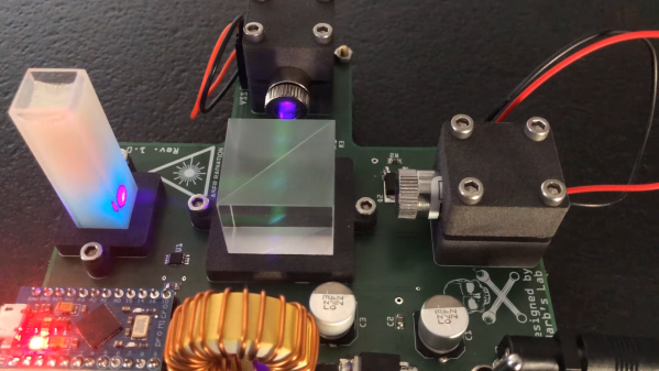
The electronics for this are pretty simple, with two laser modules and their drivers, a power supply, and an Arduino to run everything. The optics are straightforward as well — a beam splitter that directs the beams from each laser onto the target, which is a glass cuvette filled with a clear epoxy resin mixed with a photochromic chemical. [Markus] chose spiropyran as the pigment, which when bathed in UV light undergoes an intramolecular carbon-oxygen bond breakage that turns it into the dark blue pigment merocyanine. Hitting the spot with a red laser or heating the cuvette causes the C-O bond to reform, fading the blue spot.
The video below shows the intensely blue dot spot developing under UV light and rapidly fading thanks to just the ambient temperature. To make the effect last longer, [Markus] cools the target with a spritz from a CO2 cartridge. We imagine other photochromic chemicals could also be employed here, as could some kind of photometric sensor to read the current state of the flip-flop. Even as it is, though, this is an interesting way to put chemistry and optics to work.