7000 RPM On A 3D-Printed Gearbox

[Steven] at the 3D Printer Academy has been working on a variety of different gear designs. He recently embarked on a series of experiments to see how fast he can spin a 3D-printed gearbox.

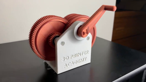
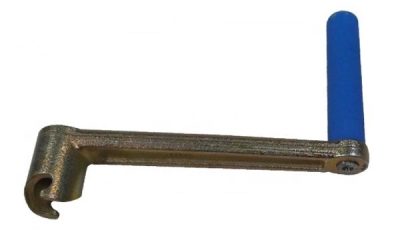
After testing several kinds of gear teeth, gear diameters, and gear spacing, he finally struck upon an 81:1 ratio gearbox. It has six gears: five stepped gears and one drive gear on the input shaft. First tests are accomplished with a 3D-printed handle, similar to a hand crank used to start really old cars. But unlike those cranks, [Steven]’s doesn’t have any release provision. While the handle can be removed, it can’t be removed while spinning.

We think it would be helpful to revise the drive shaft coupling method, allowing the handle or drill to be easily removed from the gearbox once it’s attained speed. This would be more convenient, and it seems prudent from the workbench safety point of view as well.

Example of a crank quick release mechanism

[Steven] manages to get the final gear spinning at 7000 RPM in video #2 of the series by hand cranking it “as fast as he can”, a speed measured by using the metronome app on his smartphone. He begins driving the gearbox with an electric drill in video #3, with some mixed but promising results. We think he will ultimately succeed in his goal of a high-speed, electric-drill-driven gearbox after a few more tests. If you want to have a go at this yourself, the design files are posted online.

How fast do you think he can eventually get this gearbox spinning? Are there any physical limitations of the assembly or due to the 3D printing materials/process? We certainly know that high torque can tear 3D-printed gearboxes apart, but how does the speed affect things? Let us know in the comments below.

Continue reading “7000 RPM On A 3D-Printed Gearbox”

[Ken Shirriff] Picks Apart Mystery Chip From Twitter Photo

It’s no secret that the work of [Ken Shirriff] graces the front pages of Hackaday quite frequently. He’s back again, this time reverse engineering a comparator chip from a photo on Twitter. The mysterious chip was decapped, photographed under a microscope, and subsequently posted on the internet with an open call to figure out what it did.

[Ken] stepped up, and at first glance, it was obvious that most of the chip is unused, and there appeared to be four copies of the same circuit. After identifying resistors and the different transistor types, [Ken] found differential pairs.

Differential pairs form the heart of most op-amps, and by chaining them together, you can get a strong enough signal to treat it as a logic signal. Based on the design and materials, [Ken] estimates the chip is from the 1970s. Given that it appears to be ECL (Emitter-Coupled Logic), it could just be four comparators. But there are still a few things that don’t add up as two comparators have additional inverted outputs. Searching the part number offered few if any clues, so this will remain somewhat a mystery.

We’ve covered [Ken’s] incredible chip sleuthing before here, such as the Sharp EL-8 from 1969.

Was Novell’s NE2000 Really That Bad?

If you used almost any form of networked PC in the late 1980s or the 1990s, the chances are that you will at some point have encountered the Novell NE2000 network card. This 16-bit ISA card became a de facto standard for 16-bit network cards, such that very few “NE2000” cards were the real thing. A host of clones filled the market, some of which followed the spec of the original rather loosely. It’s something [Michal Necasek] examines as he takes the reader through the history of the NE2000 and why it gained something of a bad reputation. An interesting read for ’90s PC veterans who battled with dodgy Windows 3.1 network drivers.

The Novell line of network cards were not a primary product of the network server OS company but an attempt to spur the uptake of networked computers in an age when few machines were supplied from the factory with a network card installed. They were largely an implementation of the reference design for the National Semiconductor DP3890 Ethernet interface chipset, and for simplicity of interfacing and drivers they used an I/O mapped interface rather than DMA. The problem with the NE2000 wasn’t the card itself which would work with any NE2000 driver, but the host of “NE2000 compatible” cards that appeared over the decade as that magic phrase became a key selling point at the bottom end of the market. Sure they might contain a DP3890 or its clones, but even minor differences in behaviour would cause them not to work with all drivers, and thus they gained a bad name. The piece reveals the original card as one that might have been slow and outdated towards the end of its reign as a standard card, but maybe one not deserving of the ire directed at it.

If ancient networking kit is your thing, we’ve got some far more obscure stuff to show you.

A Modern Mac Using An Ancient Mac Display

If you own an Apple product you probably live in a world with a few proprietary interfaces, but by and large your displays and desktop peripherals will use familiar ports such as USB and DisplayPort. For the Mac owner of yore though it was a different matter, as [Dandu] is here to tell us with the tale of a vintage Apple monochrome CRT monitor and a modern Mac.

There are no handy VGA ports to be found in this screen, instead it has a 15-pin D connector following a proprietary interface. With the right adapter it’s easy enough to produce VGA from the modern machine, but while it is in theory possible to map VGA pins to Apple pins there’s a snag with this particular model. Instead of using separate sync pins, it demands a composite sync of the type you might find in an analogue TV set that contains both horizontal and vertical sync pulses. The solution came through a simple transistor circuit, and then with the requisite settings on the modern Mac to deliver the 640×480 resolution it was possible to see a MacOS Catalina desktop on something more suited to a Mac II.

We’re more used to seeing CRT Macs in the form of the venerable SE/30, a machine that’s been on our radar for a long time.

Virtual Reality Experiment Tricks Your Feet Into Walking While Sitting Down

The whole idea behind virtual reality is that you don’t really know what’s going on in the world around you. You only know what your senses tell you is there. If you can fake out your vision, for example, then your brain won’t realize you are floating in a tank providing power for the robot hordes. However, scientists in Japan think that you can even fool your feet into thinking they are walking when they aren’t. In a recent paper, they describe a test they did that combined audio cues with buzzing on different parts of the feet to simulate the feel of walking.

The trick only requires four transducers, two on each foot. They tested several different configurations of what the effect looked like in the participant’s virtual reality headgear. Tests were performed in third person didn’t cause test subjects to associate the foot vibrations with walking. But the first-person perspective caused sensations of walking, with a full-body avatar working the best, compared to showing just hands and feet or no avatar at all.

Making people think they are walking in VR can be tricky but it does explain how they fit all that stuff in a little holodeck. Of course, it is nice if you can also sense walking and use it to move your avatar, but that’s another problem.

Clay Pot MP3 Player Whipped Up With The Freedom-K64F

In the streaming era, few of us think about MP3s on a day to day basis anymore. Our music collection is managed by warring executives in streaming companies from far-off lands. However, for [vinod], they’re still useful — seeing as he just built himself an MP3 player that fits in a clay pot.

The build is based on the FRDMK64F development board, packing a powerful 120 MHz ARM chip. This has enough grunt to decode MP3s on the fly, using the Helix MP3 decoder library. The MP3s themselves are streamed off an SD card, using the faster SDIO access method rather than relying on slower SPI. Once decoded, the resulting PCM audio data is shifted out via a DAC using the chip’s DMA hardware, allowing for smooth, glitch-free playback. Output to a big woofer is via a 15 W class D amplifier, with the whole rig powered from a USB powerbank.

With all the electronics piled on the back of a big woofer speaker with lashings of hot glue, the final result is quite imposing; all the more so when installed neatly inside a clay pot acting as a bass reflex enclosure. We’ve seen some concrete cast speakers before, but not nearly enough hacker projects in clay. Please rectify this, and inform us once you’ve done so. Thanks in advance — video after the break!

Continue reading “Clay Pot MP3 Player Whipped Up With The Freedom-K64F”

Fail Of The Week: Mistaking Units For Values

Usually when we post a Fail Of The Week, it’s a heroic tale of a project made with the best of intentions that somehow failed to hit its mark. The communicator that didn’t, or the 3D-printed linkage that pushed the boundaries of squirted plastic a little bit too far. But today we’re bringing you something from a source that should be above reproach, thanks to [Boldport] bringing us a Twitter conversation between [Stargirl] and [Ticktok] about a Texas Instruments datasheet.

The SN65220 schematic

The SN65220 is a suppressor chip for USB ports, designed to protect whatever the USB hardware is from voltage spikes. You probably have several of them without realising it, the tiny six-pin package nestling on the PCB next to the USB connector. Its data sheet reveals that it needs a resistor network between it and the USB device it protects, and it’s this that is the source of the fail.

There are two resistors, a 15kO and a 27O, 15k ohms, and 270 ohms, right? Looking more closely though, that 27O is not 270 with a zero, but 27O with a capital “O”, so in fact 27 ohms.

The symbol for resistance has for many decades been an uppercase Greek Omega, or Ω. It’s understood that sometimes a typeface doesn’t contain Greek letters, so there is a widely used convention of using an uppercase “R” to represent it, followed by a “K” for kilo-ohms, an “M” for mega-ohms, and so on. Thus a 270 ohm resistor will often be written as 270R, and 270 kilo-ohm one as 270K. In the case of a fractional value the convention is to put the fraction after the letter, so for example 2.7kilo-ohms becomes 2K7. For some reason the editor of the TI datasheet has taken it upon themselves to use an uppercase “O” to represent “Ohms”, leading to ambiguity over values below 1 kilo-ohm.

We can’t imagine an engineer would have made that choice so we’re looking towards their publishing department on this one, and meanwhile we wonder how many USB devices have gone to manufacture with a 270R resistor in their data path. After all, putting the wrong resistor in can affect any of us.