It is incredibly interesting how many parts of a computer system are capable of leaking data in ways that is hard to imagine. Part of securing highly sensitive locations involves securing the computers and networks used in those facilities in order to prevent this. These IT security policies and practices have been evolving and tightening through the years, as malicious actors increasingly target vital infrastructure.
Sometimes, when implementing strong security measures on a vital computer system, a technique called air-gapping is used. Air-gapping is a measure or set of measures to ensure a secure computer is physically isolated from unsecured networks, such as the public Internet or an unsecured local area network. Sometimes it’s just ensuring the computer is off the Internet. But it may mean completely isolating for the computer: removing WiFi cards, cameras, microphones, speakers, CD-ROM drives, USB ports, or whatever can be used to exchange data. In this article I will dive into air-gapped computers, air-gap covert channels, and how attackers might be able to exfiltrate information from such isolated systems.
I have a confession to make. I enjoy the challenge of squeezing software into a tiny space or trying to cut a few more cycles out of a loop. It is like an intricate puzzle. Today, of course, there isn’t nearly as much call for that as there used to be. Today even a “small” microcontroller has a ton of memory and resources.
Even so, there’s still a few cases where you need to squeeze those last few bytes out of memory. Maybe you are trying to maximize memory available for some purpose. Maybe you are anticipating mass production and you are using the smallest microcontroller you can find. Or maybe you’re doing the 1 kB Challenge and just want some advice.
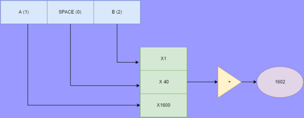
One way to find techniques to maximize resources is to look at what people did “in the old days.” Digital Equipment computers once had a special character set called Squoze (or sometimes DEC Radix-50). This technique can be useful when you need to get a lot of strings into memory. The good news is that you can reliably get 3 characters into 2 bytes (or, as DEC did, 6 characters into 4 bytes). The bad news is that you have to pick a limited character set that you can use. However, that’s not always a big problem.
Although I’ve been to several DEF CONs over the past few years, I’ve never found time to devote to solving the badge. The legendary status of all the puzzles within are somewhat daunting to me. Likewise, I haven’t yet given DefCon DarkNet a try either — a real shame as the solder-your-own-badge nature of that challenge is right up my alley.
But at the Hackaday SuperCon I finally got my feet wet with the crypto challenge created by [Marko Antonic]. The challenge was built into a secondary firmware which anyone could easily flash to their conference badge (it enumerates as a USB thumb drive so just copy it over). This turned it into a five-puzzle challenge meant to take two days to solve, and it worked perfectly.
Thar’ be spoilers below. I won’t explicitly spill the answers, but I will be discussing how each puzzle is presented and the different methods people were using to finish the quest. Choose now if you want to continue or wait until you’ve solved the challenge on your own.
As hackers and makers we are surrounded by accessible computing in an astonishing diversity. From tiny microcontrollers to multi-processor powerhouses, they have become the universal tool of our art. If you consider their architecture though you come to a surprising realisation. It is rare these days to interface directly to a microprocessor bus. Microcontrollers and systems-on-chip have all the functions that were once separate peripherals integrated into their packages, and though larger machines such as your laptop or server have their processor bus exposed you will never touch them as they head into your motherboard’s chipset.
A few decades ago this was definitely not the case. A typical 8-bit microprocessor of the 1970s had an 8-bit data bus, a 16-bit address bus, and a couple of request lines to indicate whether it wanted to talk to memory or an I/O port. Every peripheral you connected to it had to have some logic to decode its address and select it when you wanted to use it, and all shared the processor’s bus. This was how those of us whose first computers were the 8-bit machines of the late 1970s and early 1980s learned the craft of computer hardware, and in a world of Arduino and Raspberry Pi this now seems a lost art.
The subject of today’s review then provides a rare opportunity for the curious hardware hacker to get to grips with a traditional microprocessor bus. The RC2014 is a modular 8-bit computer in which daughter cards containing RAM, ROM, serial interface, clock, and Z80 processor are ranged on a backplane board, allowing complete understanding of and access to the workings of each part of the system. It comes with a ROM BASIC, and interfaces to a host computer through a serial port. There is also an ever-expanding range of further peripheral cards, including ones for digital I/O, LED matrixes, blinkenlights, a Raspberry Pi Zero for use as a VDU, and a small keyboard.
When the story of an invention is repeated as Received Opinion for the younger generation it is so often presented as a single one-off event, with a named inventor. Before the event there was no invention, then as if by magic it was there. That apple falling on Isaac Newton’s head, or Archimedes overflowing his bath, you’ve heard the stories. The inventor’s name will sometimes differ depending on which country you are in when you hear the story, which provides an insight into the flaws in the simple invention tales. The truth is in so many cases an invention does not have a single Eureka moment, instead the named inventor builds on the work of so many others who have gone before and is the lucky engineer or scientist whose ideas result in the magic breakthrough before anyone else’s.
The history of computing is no exception, with many steps along the path that has given us the devices we rely on for so much today. Blaise Pascal’s 17th century French mechanical calculator, Charles Babbage and Ada, Countess Lovelace’s work in 19th century Britain, Herman Hollerith’s American tabulators at the end of that century, or Konrad Zuse’s work in prewar Germany represent just a few of them.
So if we are to search for an inventor in this field we have to be a little more specific than “Who invented the first computer?”, because there are so many candidates. If we restrict the question to “Who invented the first programmable electronic digital computer?” we have a much simpler answer, because we have ample evidence of the machine in question. The Received Opinion answer is therefore “The first programmable electronic digital computer was Colossus, invented at Bletchley Park in World War Two by Alan Turing to break the Nazi Enigma codes, and it was kept secret until the 1970s”.
It’s such a temptingly perfect soundbite laden with pluck and derring-do that could so easily be taken from a 1950s Eagle comic, isn’t it. Unfortunately it contains such significant untruths as to be rendered useless. Colossus is the computer you are looking for, it was developed in World War Two and kept secret for many years afterwards, but the rest of the Received Opinion answer is false. It wasn’t invented at Bletchley, its job was not the Enigma work, and most surprisingly Alan Turing’s direct involvement was only peripheral. The real story is much more interesting.
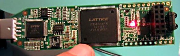
Over the last year we’ve had several posts about the Lattice Semiconductor iCEstick which is shown below. The board looks like an overgrown USB stick with no case, but it is really an FPGA development board. The specs are modest and there is a limited amount of I/O, but the price (about $22, depending on where you shop) is right. I’ve wanted to do a Verilog walk through video series for awhile, and decided this would be the right target platform. You can experiment with a real FPGA without breaking the bank.
In reality, you can learn a lot about FPGAs without ever using real hardware. As you’ll see, a lot of FPGA development occurs with simulated FPGAs that run on your PC. But if you are like me, blinking a virtual LED just isn’t as exciting as making a real one glow. However, for the first two examples I cover you don’t need any hardware beyond your computer. If you want to get ready, you can order an iCEstick and maybe it’ll arrive before Part III of this series if published.
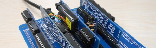
There comes a time when you need to wire up three, four, or more identical i2c devices to a common microcontroller. Maybe you’re thinking about driving 128 seven-segment displays with eight of those MAX6955 16-way digit drivers, or maybe you have a robot full of joints–each of which needs a BNO055 inertial sensor for angle estimation. (See above.) Crikey! In both of those cases, you’re best bet might be a schnazzy I²C device that can do most of the work for you. The problem? With a single I²C bus, there’s no standard way defined in the protocol for connecting two or more devices with the same address. Shoot! It would’ve been handy to wire up three BNO055 IMUs or eight MAX6955s and call it a day. Luckily, there’s a workaround.
We’ve seen some clever tricks in the past for solving this problem. [Marv G‘s] method involves toggling between a device’s default and alternate address with an external pin. This method, while clever, assumes that the device (a) has an alternate I²C address and (b) features an external pin for toggling that address.
I’ll introduce two additional methods for getting the conversation started between your micro’ and your suite of identical sensors. The first is “a neat trick,” but somewhat impractical for widespread use. The second is far more production-worthy–something you could gloat over and show off to your boss! Without further ado, let’s get started with Method 1.
Lastly, if you’d like to follow along, feel free to check out the source code on Github.
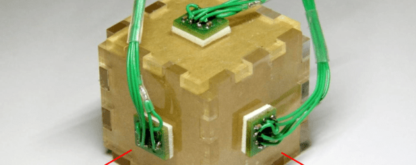
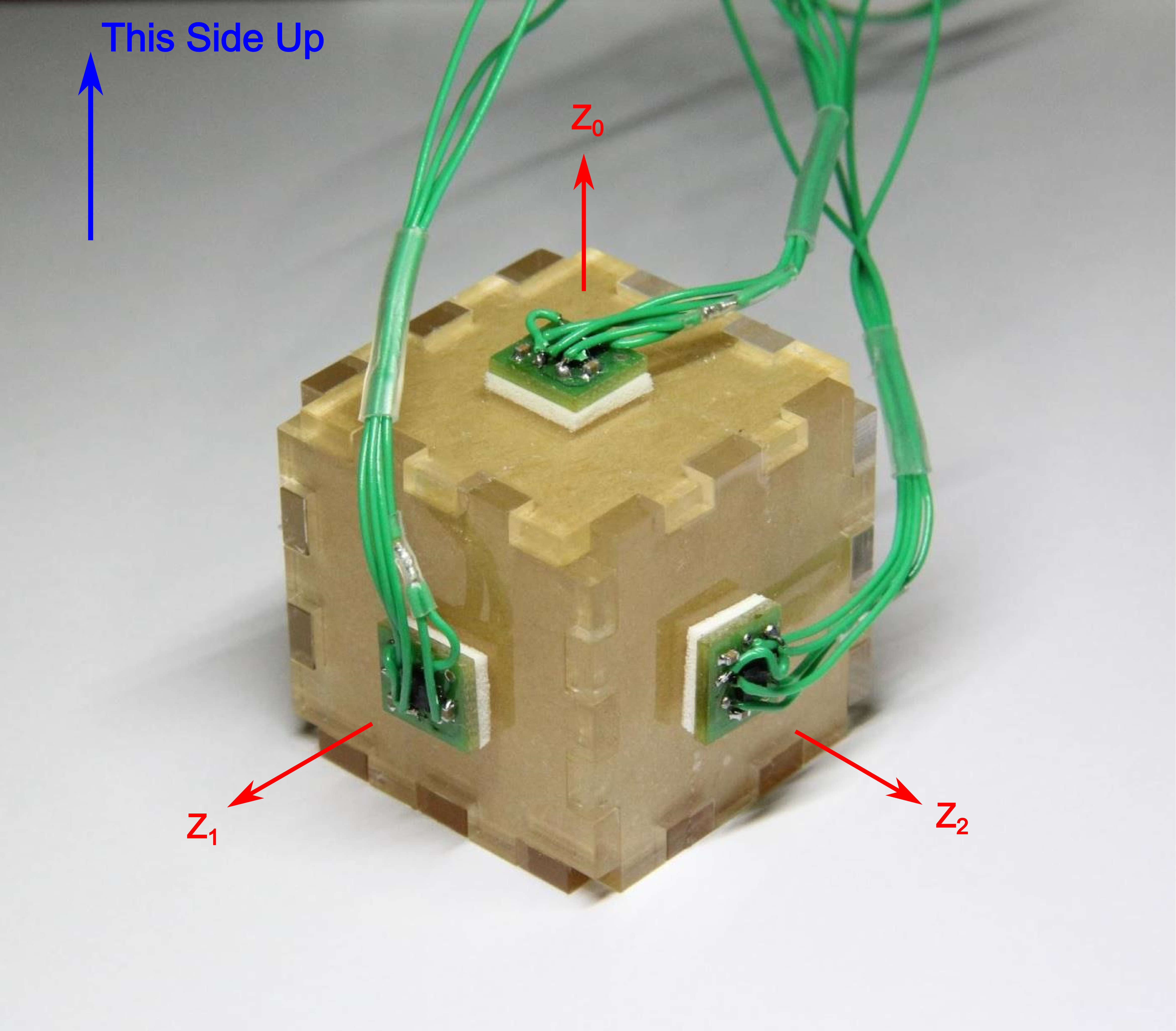
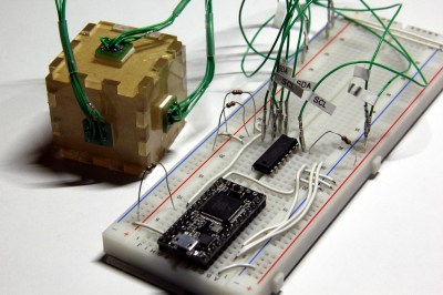
In both methods, I’m using the same sensor setup to check that each circuit behaves correctly. I happened to have a bunch of extra BMA180s on the bench, so I rolled out an example based on these chips. Back in the day, the BMA180 was a pretty common three-axis digital accelerometer. It has an I²C interface with two optional addresses. For the purpose of this example, I’m fixing them all with the same address. I’ve mounted three of these guys on mutually perpendicular axes of my acrylic “test cube,” and I’m reading each chip’s Z-axis. In this configuration I can easily pick out the gravity vector from the corresponding sensor as the data goes flying by my serial port window. If I can uniquely address each sensor and read the data, I’ve got a working circuit.
Method 1: Splicing Clocks into Chip-Selects
This method tips its hat towards SPI in that it behaves in an oddly similar fashion. If you’re feeling rusty on SPI, here’s a quick recap.
A Quick SPI Refreshment:
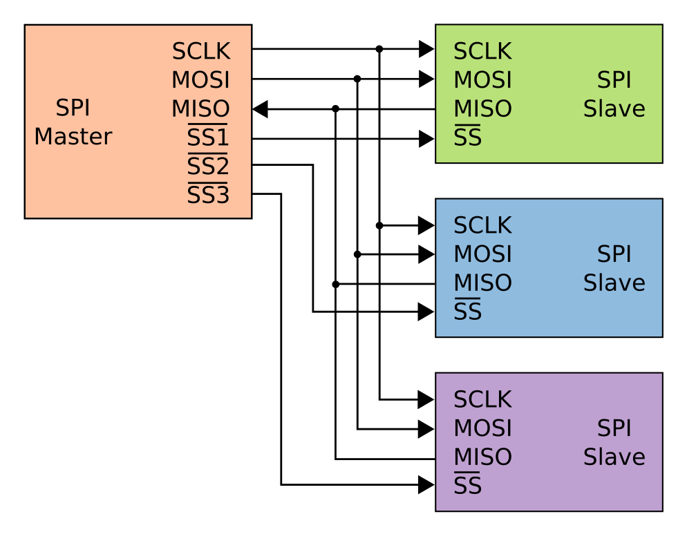
SPI, like I²C, is another protocol that shares both its clock and data lines with multiple slave devices. The difference, though, lies in the addressing scheme to talk to these devices that share the same bus. With SPI, while clock and data lines are shared, devices are addressed with separate chip-select (CS) lines.
The master microcontroller dedicates a unique output pin to each device (~SS1, ~SS2, and ~SS3 in this illustration). When the master micro’ wants to talk to a device, it asserts that device’s chip-select input pin by pulling it to logic LOW, and the conversation begins over the data bus. With the chip select LOW, the corresponding slave listens to the data on the bus. Meanwhile, all other devices ignore the conversation between the master and it’s chosen slave by keeping their bus pins in a high impedance state.
Giving I²C Its Own Chip-Selects:
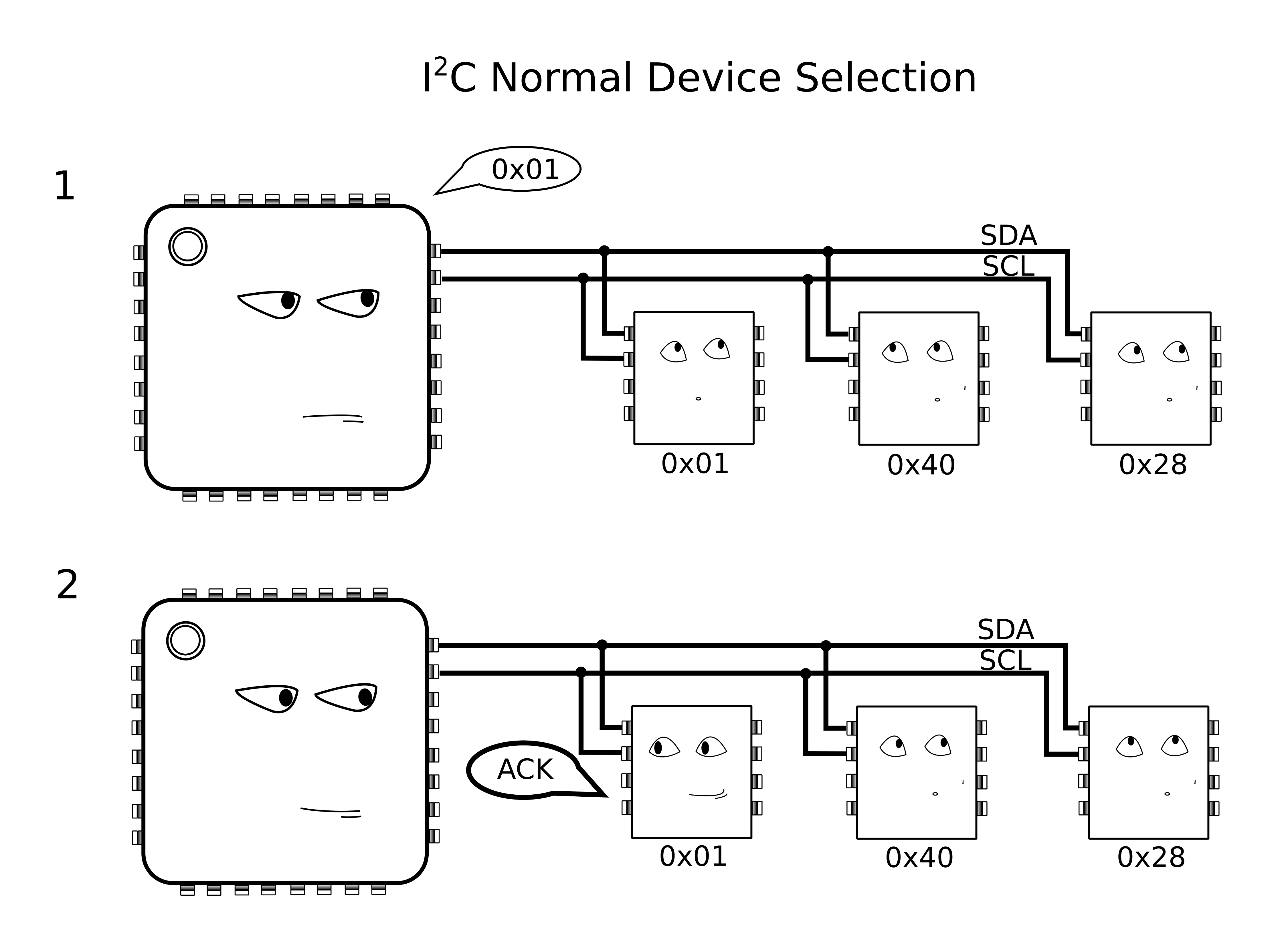
With I²C, Clock (SCL) and Data (SDA) lines are still shared between all I2C slave devices, but the addressing scheme happens by sending a message heard by all devices on the bus. To single out one device on the shared bus, the master first passes down the address of the slave device it wants to talk to, after which that slave replies with an ACKnowledge, and all other slaves ignore the data that follows until both data transmission is complete and the bus is “released.”
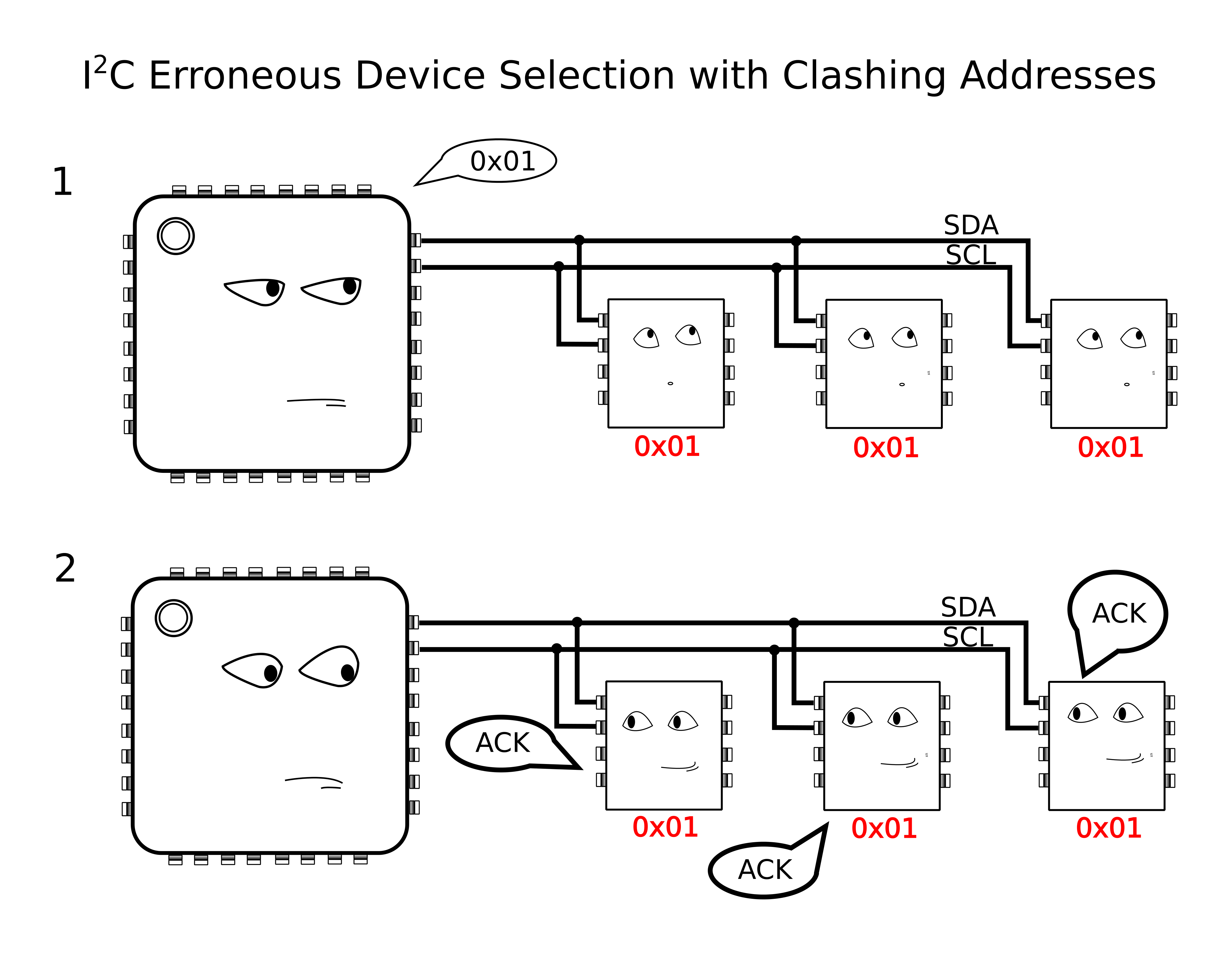
Because we have the problem of multiple devices with shared addresses, in theory, all of these devices would reply when the master passes down their shared address, and there’s no way for the master to single out a single device. In reality, this behavior is undefined on the I²C protocol.
Yikes! Anything goes when we wander away from defined behavior, so we try to avoid these things in practice.
The solution?
According to the I²C spec, It just so happens that an I²C slave device will ignore changes on the data line (SDA) provided that the clock line (SCL) is held high. In this method, I’ll “split” the SCL line into multiple SCL lines such that each shared I²C device gets its own SCL. By selectively rerouting the clock to each I²C device one-at-a-time, I’ve essentially turned the SCL line into a “chip select.”
To chop up that clock line, I’ll need a demultiplexer. A demultiplexer (or decoder) takes a logical input and reroutes it to one of several outputs based on the binary select lines.
I’ve dropped in the 74AC11138 eight-way demultiplexer for this task. It’s fast, capable of switching at megahertz rates, and its outputs default to logic HIGH. That second note is handy since idle SCL lines also default to logic HIGH.
The setup is shown in a simplified schematic above. In it, I’m using a Teensy 3.0 posing as the I²C bus master. To the right of the Teensy is the collection of identical chips, BMA180 accelerometers in this case. In the middle is the 74AC11138 eight-way demultiplexer.
Cons of this Method:
There’s a minor drawback with this technique, though, in that it doesn’t support I²C’s clock-stretching feature. Taking a step back, this method assumes that the SCL line is inherently unidirectional, controlled by only the I²C bus master. In other words, we’re making the assumption that data on the SCL line is only sent from master to slave and never the other way around. If your I²C slave devices implement clock-stretching, however, this assumption breaks down.
What is Clock Stretching?
Clock stretching is a method defined by the I²C protocol where the chip needs to “buy itself more time” and holds the SCL line low, hence, signalling to the master that it’s not ready for the upcoming data. In this scenario, the slave actively controls the SCL line, and it happens to be the only case where data moves up the SCL line from slave to master. In a setup with our demultiplexer between the master and our set of identical slaves, these slaves won’t be able to send back the clock-stretching signal to the master to indicate that they aren’t ready for data, if they happen to implement clock stretching. That said, clock stretching is a pretty rare feature among I²C-compatible devices, so this method is likely to work among a number of chips out now.
More Next Week
That’s all for Method 1. Thanks for tuning in, and check back next week for a slightly-more-professional method of tackling this same problem.


 I’ve dropped in the 74AC11138 eight-way demultiplexer for this task. It’s fast, capable of switching at megahertz rates, and its outputs default to logic HIGH. That second note is handy since idle SCL lines also default to logic HIGH.