About a decade ago, the only way the average hacker was getting their hands on a desktop 3D printer was by building it themselves from a kit. Even then, to keep costs down, many of these kits were made out of laser cut wood. For a few years, wooden printers from companies like MakerBot and PrintrBot were a common sight in particularly well equipped hackerspaces. But as the market expanded and production went up, companies could afford to bend metal and get parts injection molded; the era of the wooden 3D printer was over nearly as soon as it had started.
 But [Luke Wallace] thinks there’s still some life left in the idea. For his entry into the 2019 Hackaday Prize, he’s proposing a revival of the classic laser cut 3D printer kit. But this time, things are a bit different. Today, laser cutters are cheap enough that these kits could conceivably be manufactured at your local hackerspace. With a total bill of materials under $100 USD, these kits could be pumped out for less than the cheapest imports, potentially driving adoption in areas where the current options are too expensive or unavailable.
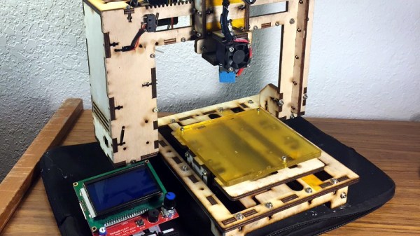
Of course, just a laser cut wood frame wouldn’t be enough to break the fabled $100 barrier. To drive the cost down even farther, [Luke] has redesigned essentially every component so it could be made out of wood. If its not electronic, there’s a good chance its going to be cut out of the same material the frame is made out of. Probably the biggest change is that the traditional belt and pulley system has been replaced with rack and pinion arrangements.
After cutting all the pieces, essentially all you need to provide is the stepper motors, a RAMPS controller, the hotend, and the extruder. He’s even got a design for a laser cut wood extruder if you want to go back to the real olden days and save yourself another few bucks. Or skip the LCD controller and just run it over USB.
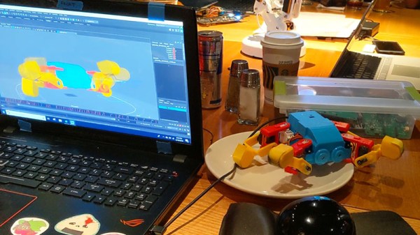
But what do the prints look like? [Luke] has posted a few pictures of early test pieces on the project’s Hackaday.io page, and to be honest, they’re pretty rough. But they don’t look entirely unlike the kind of prints you’d get on one of those early printers before you really got it dialed in, so we’re interested in seeing how the results improve with further refinements and calibration. (Editor’s note: Since writing this, he got backlash compensation up and running, and it looks a ton better already. Very impressive for something running on wooden gears!)