Over the years, readers have often commented that microcontrollers (or more specifically, the Arduino) are overkill for many of the projects they get used in. The admonition that the creator “Should have used a 555” has become something of a rallying cry for those who think modern electronic hobbyists are taking the easy way out.
 But what if you think even the lowly 555 timer is overkill? In that case, perhaps you’ll be interested in a recent blog post by [TheMagicSmoke], where the reader is walked through the process of creating an analog of the classic integrated circuit on a somewhat larger scale. Finally, we can replace that cheap and handy IC with a mass of wires and components.
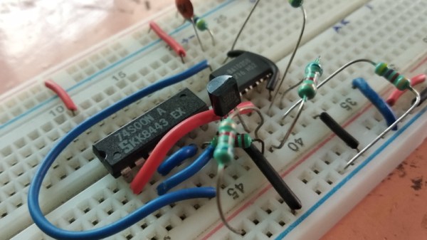
Alright, so you’ve probably guessed that there’s no practical reason to do this. Outside of some theoretical MacGyver situation in which you needed to create a square wave using parts salvaged from devices laying around, anyway. Rather, the project is presented as a good way to become more confident with the low-level operation of electronic circuits, which is something we think everyone can agree is a good thing.
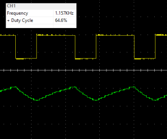
The components used include a 74S00 quad NAND gate, a LM358 dual operational amplifier, a 2N2222A transistor, and a handful of passive components. [TheMagicSmoke] not only explains how the circuit is constructed, but shows the math behind how it all works. Finally, an oscilloscope is used to verify it’s operating as expected.
We respect a hacker on a mission, just last month [TheMagicSmoke] put together a similar “back to basics” post on how to interface with an I2C EEPROM.
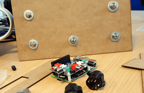
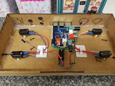 At the center of the box is a Raspberry Pi with an AudioInjector stereo sound card. The card takes care of stereo in and out, and passing the signal to the Pi. The software is Modep, an open source audio processor that allows the setup of a chain of digital effects plugins to be run on the Pi. After finding some foot switches, [Craig] connected them to an Arduino Pro Micro which he set up as a MIDI device that sends MIDI messages to the Modep software running on the Pi.