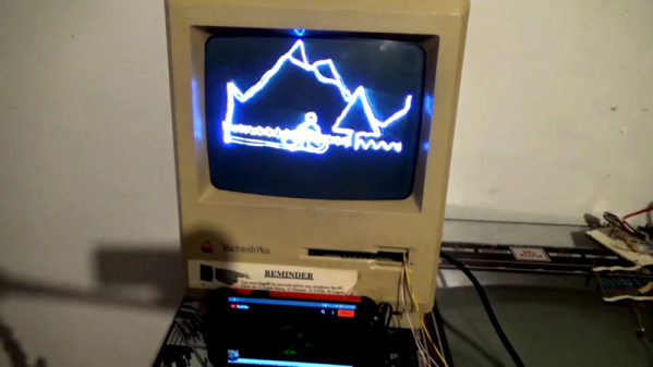
The vintage Macintosh all-in-one computers were a design icon, as well as being highly useful machines in the 80s and 90s. In the decades since, they’ve been used for everything from web servers to aquariums, but that’s not all. [Arcade Jason] decided to grab an old Macintosh Plus and turn it into a vector display.
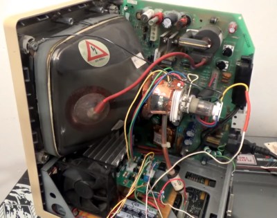 The hack starts with the opening of a Macintosh, which naturally requires a long screwdriver with the right tip. Setting the stage for things to come, this is achieved by soldering together a couple of existing tools to get the reach he needs. [Jason] then proceeds to install a brightness control for the main electron gun, as well as deflection drivers and a spot killing circuit. Everything is done with the intention of the hack being reversible, as [Jason] didn’t wish to sacrifice a good Macintosh Plus just for the sake of having some fun.
For those unfamiliar with vector cathode-ray displays and the manner in which they are driven, [Arcade Jason] does a great job explaining the basics. A set of magnetic coils is used to alter the trajectory of an electron fired at the screen. If you aim those electrons in ordered lines from left-to-right, top-to-bottom you’ve created a raster display. If you instead guide the electrons to follow the shapes you want to appear on the screen you’ve created a vector display.
We can’t help but feel this would be a hilarious way to troll at a demoscene meetup. We’ve seen [Jason]’s vector work before, too — like this impressive color Asteroids hack.