The speaker in the original IBM PC is nearly the worst electronic musical instrument ever created. This isn’t because amazing works of art were never created for the PC speaker; no, that’s been done, and it’s amazing. The PC speaker is terrible because of how limited it is. It does one note at a time, only square waves, driven by an 8253 Programmable Interval Timer. Polyphony? Forget about it. Volume control? Nope. These aren’t really shortcomings, because music is art, and you can write a novel without using the letter ‘E’; the trick is in how you manage to do it.
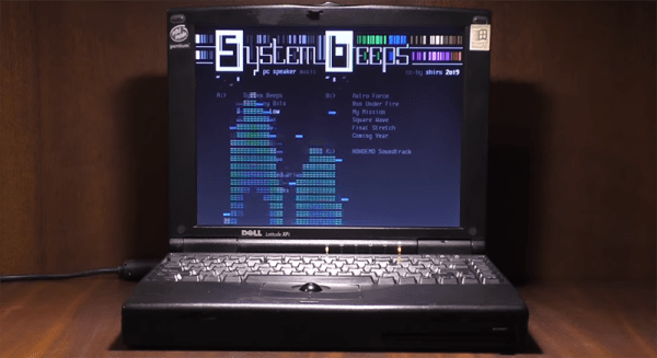
[shiru8bit] took a deep dive into the PC speaker and decided to make an album. The video, with the completely necessary CRT graphic display, can be seen here. This alone is impressive, but what makes it amazing is how this album happened.
If you want to play more than a simple melody on a PC speaker, there are two or two and a half ways to do it. The first is to (virtually) set up two (or more) channels, loaded up with frequency values. At set intervals, the CPU changes the 8253 to output one frequency, then in the next chunk of time, sets the 8253 to another frequency. It sounds ‘bubbly’ for lack of a better term, but the results can be amazing; just check out the PC speaker version of Monkey Island. The 8253 can also be turned into a rudimentary DAC, but this was a rare technique thanks to patents, and by the time the patents expired everyone already had a Soundblaster. Oh well.
[shiru8bit]’s album uses the first technique, cycling through monophonic square waves at 120 Hz, but the real trick here is how the individual channels were composed. This required creating a VSTi plugin called PCSPE. This emulates a PC speaker, and sort of, kind of, implements arpeggios, pitch, and priority of different channels. Effectively, it’s a PC Speaker tracker.
The result is classic chiptune goodness, made on an instrument that really shouldn’t be used for music. It can be played on DosBox, but the weirdness of the real hardware including transients and the inefficiencies of a tiny speaker make real hardware almost a necessity here. You can check out the entire album below.