Whether it was home-built from scraps or one of the various commercial versions that have popped over up over the years, there’s an excellent chance that the average Hackaday reader spent at least a couple of their more formative summers flying water rockets. You might not have realized it at the time, but with shirt soaked and head craned skywards, you were getting a practical physics lesson that was more relatable than anything out of a textbook. Water rockets are a great STEM tool for young people, but in a post-Fortnite world, the idea could use a little modernization to help keep kids engaged.
 With his entry into the 2019 Hackaday Prize, [Darian Johnson] hopes to breathe some new life into this classic physics toy. His open source kit would provide a modular water rocket intended for a wide range of ages thanks to various payloads and upgrade options. The younger players would be content to simply see it take off, but high school students could outfit the craft with an electronic payload to capture performance data or an automatic parachute.
[Darian] has been building and flying rockets with his own children and other youth in community for years now, and has found them to be a huge hit. They became so popular that he started thinking of a way to not produce them in larger quantities, but make them stronger so they would survive more flights.
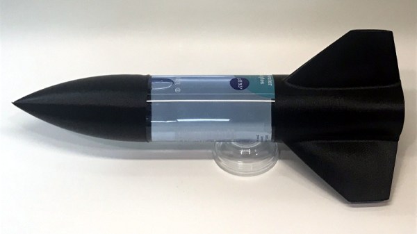
Of course, the fuselages are easy enough; there’s no shortage of one-liter bottles you can recycle. But for the nose cone, fins, and ultimately even the launch pad, [Darian] turned to 3D printing. This allows him to continually optimize the design while delivering repeatable performance. When he had a semi-printable water rocket on his hands, he started to wonder if he could get older kids interested by adding some electronics into the mix.
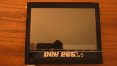
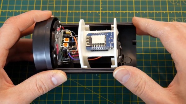
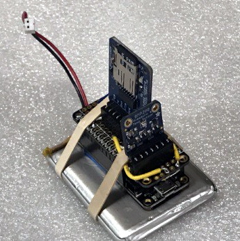
His current proof of concept is a flight data recorder using a Adafruit nRF52 Bluefruit LE Feather, a BMP280 sensor to determine altitude via barometric pressure, and an SD card breakout for local data storage. Long term, [Darian] wants to be able to stream flight data to student’s phones over Bluetooth, with the SD card providing a local copy which can be analyzed after the flight.
[Darian] has leaned heavily on the open source community for the various components of his water rocket kit, and is dedicated to giving back. He hopes that his final kit will allow communities to create engaging STEM activities at little to no cost. This includes creating a repository of lesson plans and designs contributed from others experimenting with water rockets. It’s a noble goal, and we’re excited to see how the project progresses.