ESP8266 Zelda Heart Responds To Tweets

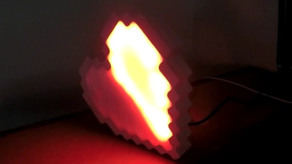
It might not be enough to make you the Hero of Time, but this piece of Hylian interactive art would still be a worthy addition to your game room. [Jeremy Cook] writes in to tell us about how he put together this 8-bit style heart display, and goes into enough detail on the hardware and software sides of things that you shouldn’t have any problem adapting his design for your own purposes.

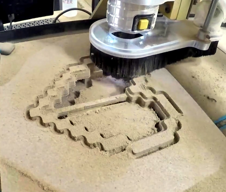
The build is pretty simple overall but it does assume you have a CNC to cut the basic shape out of MDF. You could cut the shape by hand if you had to, but if you don’t have a CNC the next best thing might be to 3D print the case. You’d potentially have to print it in two parts right down the center though, depending on how big your bed is. Whichever way you create the case, you’ll then need to cut the shape out of a piece of acrylic to make the face.

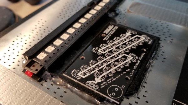
In any event, once the pieces are cut out [Jeremy] adds in a Wemos D1 Mini, a power supply, and some red LED strips. He provides a wiring diagram, but it’s fairly straightforward stuff. With a couple of 2N2222 transistors he controls the LED strips right from the digital pins of the ESP8266.

The software side is setup to be controlled via IFTTT by way of Adafruit.io. When IFTTT sees one of the keywords on Twitter, it passes a message to Adafruit.io which ultimately talks to the ESP8266 and gets the heart going. The software supports three states (on, off, and half) and gives a good example of a basic IoT implementation on the ESP8266 if you’re looking for some inspiration.

This hack seems like it would fit in perfectly with the Zelda home automation project we covered last year.

An Integrated Electromagnetic Lifting Module For Robots

The usual way a robot moves an object is by grabbing it with a gripper or using suction, but [Mile] believes that electromagnets offer a lot of advantages that are worth exploring, and has designed the ELM (Electromagnetic Lifting Module) in order to make experimenting with electromagnetic effectors more accessible. The ELM is much more than just a breakout board for an electromagnet; [Mile] has put a lot of work into making a module that is easy to interface with and use. ELM integrates a proximity sensor, power management, and LED lighting as well as 3D models for vertical or horizontal mounting. Early tests show that 220 mW are required to lift a 1 kg load, but it may be possible to manage power more efficiently by dynamically adjusting drive voltage depending on the actual load.

[Mile]’s focus on creating an easy to use, integrated solution that can be implemented easily by others is wonderful to see, and makes the ELM a great entry for The Hackaday Prize.

HOPE XII: A FOSS Operating System For E-Readers

Free and open source software (FOSS) was a recurring theme during many of the talks during the HOPE XII conference, which should probably come as no surprise. Hackers aren’t big fans of being monitored by faceless corporate overlords or being told what they can and cannot do on the hardware they purchased. Replacing proprietary software with FOSS alternatives is a way to put control back into the hands of the user, so naturally many of the talks pushed the idea.

In most cases that took the form of advising you to move your Windows or Mac OS computer over to a more open operating system such as GNU/Linux. Sound advice if you’re looking for software freedom, but it’s a bit quaint to limit such thinking to the desktop in 2018. We increasingly depend on mobile computing devices, and more often than not those are locked down hard with not only a closed proprietary operating system but also a “Walled Garden” style content delivery system. What’s the point of running all FOSS software at home on your desktop if you’re carrying a proprietary mobile device around?

That’s precisely the thinking that got Marc Juul interested in the possibility of bringing a FOSS operating system to e-reader devices. During his talk “Liberate Your E-book Reader with fread.ink!”, he gave examples such as Amazon’s infamous remote deletion of 1984 off of users’ Kindles as a perfect example of the sort of control these companies exert on our personal devices. Marc believes the goal should be to completely replace the operating system on these devices with a free software alternative that still retains the ability to open electronic book formats. Not only would this keep the likes of Amazon or Barnes and Noble out of our reading habits, but turn these cheap readers into more capable devices in the bargain.

Continue reading “HOPE XII: A FOSS Operating System For E-Readers”

Friday Hack Chat: Making Modular Hardware

The future of wireless is decentralized. Mesh-type networks are slowly making their way into the WiFi standard, and soon enough we’ll be dealing with decentralized phones. That’s wireless, but what about electronics? For most embedded work, we’re dealing with masters and slaves, but what if we didn’t have to deal with that? This is the challenge of modular electronics, and this week’s Hack Chat is going to be talking all about that.

Our guest for this week’s Hack Chat is [Asaad Kaadan], an electronics engineer from Seattle. [Asaad] holds a Masters and PhD in Electrical Engineering from the University of Oklahoma. For his day job, he builds high-end camera controllers for Freefly Systems. By night, he designs Hexabitz electronics prototyping modules. What are Hexabitz? That’s where this is about to get interesting.

Hexabitz are, as you would expect, tiny little hexagons packed with electronics. Every hexagon has a microcontroller on board, and these hexagons connect together through solder pad connectors along the edges of the board. Before you ask, yes, there are pentagonal Hexabitz, so yeah, you can do that.

During this Hack Chat, we’re going to be talking all about modular electronics and [Assad]’s Hexabits. We’re going to be covering questions like:

  • How to design connectors for testing boards
  • What the protocol for mesh electronics looks like
  • How to use modular electronics together in a system

You are, of course, encouraged to add your own questions to the discussion. You can do that by leaving a comment on the Hack Chat Event Page and we’ll put that in the queue for the Hack Chat discussion.join-hack-chat

Our Hack Chats are live community events on the Hackaday.io Hack Chat group messaging. This week is just like any other, and we’ll be gathering ’round our video terminals at noon, Pacific, on Friday, July 27th.  Need a countdown timer? Yes you do.

Click that speech bubble to the right, and you’ll be taken directly to the Hack Chat group on Hackaday.io.

You don’t have to wait until Friday; join whenever you want and you can see what the community is talking about.

Monoprice Mini Converted To Pick And Place (Kinda)

Would you believe that you can take a cheap 3D printer and easily convert it into a full function pick and place machine to help assemble your PCBs? No? Well good, because you can’t. A real pick and place needs all kinds of sensors and logic to identify parts, rotate them, make sure everything is aligned, etc, etc. There’s no way you could just bolt all that onto a cheap 3D printer, and let’s not even talk about the lack of closed loop control.

But if you have a very specific use case, namely a PCB that only has a relatively large single part that doesn’t need to be rotated, [Connor Nishijima] might have a solution for you. He bought a $150 USD Monoprice Mini, and with the addition of a few printed parts, was able to build a machine that drastically cuts down the time it takes for him to build his LED boards. Best of all the modification doesn’t involve any permanent changes to the printer, he can just pop off the vacuum attachment when he wants to print something.

Beyond the 3D printed parts (which were made on the printer itself), the only thing you need to make the modification is the vacuum pump. [Connor] is using a hot air station that includes a vacuum pump for picking up SMD components, but he mentions that you’d probably better off just modifying an aquarium pump and using that. A printed holder snaps over the cooling fan of the Monoprice Mini to hold the vacuum pickup tool, and another printed piece holds the strip of LEDs and the PCB. It’s worth noting that the machine has no ability to control the vacuum pump, and doesn’t need to. The pickup tool is so weak that when the LED lands in the solder paste it sticks to the board well enough that the tool can’t lift it back off.

The real genius in this build comes from the manually written G-Code. You load it from the printer’s built in menu system as if it was a normal 3D print, and it instructs the printer to move the vacuum tool over the line of LEDs, pick one up, and drop it in place on the PCB. It then uses a small peg built into the vacuum tool holder to advance the line of LEDs before starting the cycle all over again. Incredibly, it does this whole complex dance 20 times for each PCB without ever having any kind of feedback or alignment check. It only works because [Connor] was willing to go through the trial and error of getting the calibration and G-Code down as close to perfect as can be expected for such a cheap machine.

This isn’t the first time we’ve seen the Monoprice Mini converted into something a bit more impressive than a cheapo 3D printer. Seems that for whatever the machine lacks in the printing department, it more than makes up for in hackability.

Continue reading “Monoprice Mini Converted To Pick And Place (Kinda)”

How—And Why—To Avoid Tolerance Stacking In Your Technical Drawings

If you want to have your part designs fabricated, you’re going to need to provide the manufacturer with a technical drawing. Yes, 3D printers and many modern machine tools rely on toolpaths created from 3D models. But, there is a good chance the manufacturer will be recreating the 3D model in their own system, instead of using the one you provided. Or, they may use traditional manual machining and not touch a 3D model at all. More importantly, the technical drawing gives them vital information on how closely they need to adhere to your dimensions in order for you to accept the parts.

On a technical drawing, the dimension that you want is called the nominal. But, no manufacturing is ever perfect, so you have to allow some wiggle room in what you’ll accept. That wiggle room is called tolerance. Maybe your part could be a little longer than specified and it wouldn’t affect the functionality. Maybe it could be a little shorter—or either. Specifying a tolerance is necessary, because it tells the manufacturer exactly how much wiggle room you’re giving them.

But, tolerances can introduce unforeseen consequences if you’re not careful. The wiggle room provided by tolerances is absolutely necessary, but if you don’t use them properly you can easily end up with unusable parts, even if the manufacturer followed your instructions to the letter. That usually happens because you have multiple tolerances being added together, which is called tolerance stacking.

Continue reading “How—And Why—To Avoid Tolerance Stacking In Your Technical Drawings”

Was The Self Driving Car Invented In The 1980s?

The news is full of self-driving cars and while there is some bad news, most of it is pretty positive. It seems a foregone conclusion that it is just a matter of time before calling for an Uber doesn’t involve another person. But according to a recent article, [Ernst Dickmanns] — a German aerospace engineer —  built three autonomous vehicles starting in 1986 and culminating with on-the-road demonstrations in 1994 for Daimler.

It is hard to imagine what had to take place to get a self-driving car in 1986. The article asserts that you need computer analysis of video at 10 frames a second minimum. In the 1980s doing a single frame in 10 minutes was considered an accomplishment. [Dickmanns’] vehicles borrowed tricks from how humans drive. They focused on a small area at any one moment and tried to ignore things that were not relevant.

Continue reading “Was The Self Driving Car Invented In The 1980s?”