In our fast-paced modern world, it’s no wonder that so many suffer from anxiety and panic attacks. There are several time-worn techniques for dealing with the symptoms of these attacks. But as anyone who’s ever suffered such an attack can tell you, it can be difficult to sense one coming on until it’s too late. By then, rational thinking has been supplanted by intrusive thoughts. For this year’s Hackaday Prize, [Austin Marandos] is doing his part by using technology to help us check ourselves before we wreck ourselves with worry.
Similar smartwatches exist to detect oncoming attacks, but they don’t do anything to combat them. Minder is like having a friend strapped to your wrist that’s never absorbed in their own problems. It wants to help no matter what it takes, which is why it features multiple techniques for getting back to a state of calm.
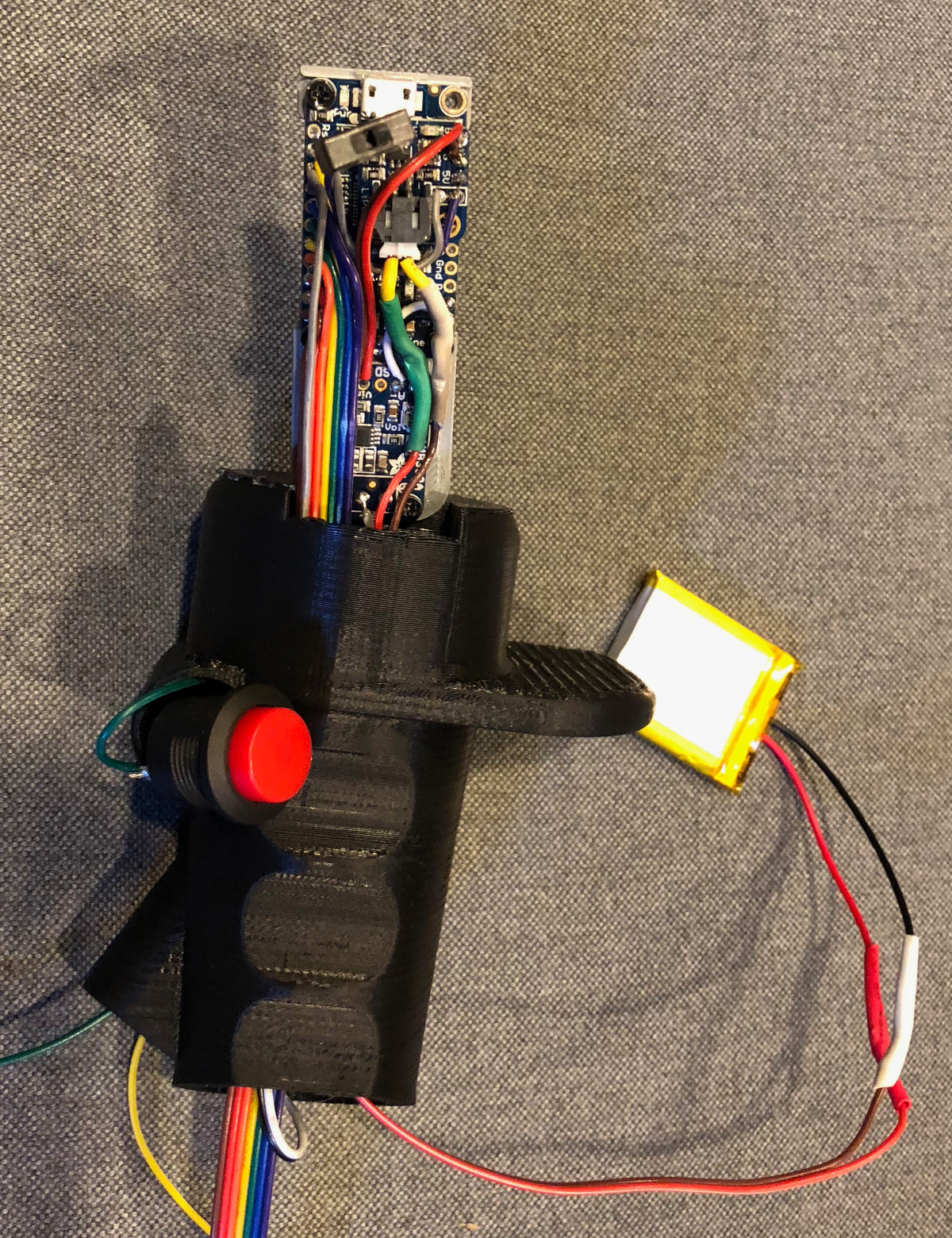
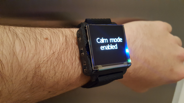
Minder’s brain is the bite-size Qduino Mini, which is great for a crowded wearable because of its built-in charging circuit. It uses heart rate and temperature sensors to determine the onset of a panic attack, and a vibration motor to alert the user. The motor also plays a part in the relaxation techniques to keep the user focused and in control. Use the upcoming break to relax and check out the video.
If your anxiety stems from feelings of inadequacy, it might be Imposter Syndrome.