Vintage Digital Frequency Meter Teardown

You think of digital displays as modern, but the idea isn’t that new. We had clocks, for example, with wheels and flip digits for years. The Racal frequency counter that [Thomas Scherrer] is playing with in the video below has columns of digits with lamps behind them. You just need the right plastic and ten lightbulbs per digit, and you are in business. Easy enough to accomplish in 1962.

Inside the box was surprising. The stack of PC boards looks more like a minicomputer than a piece of test gear. There were a few novel items inside, too, ranging from a glass-encapsulated crystal to an interesting method of selecting the line voltage.

Continue reading “Vintage Digital Frequency Meter Teardown”

Do Not Attempt Disassembly: Analog Wizardry In A 1960s Counter

[CuriousMarc] is back with more vintage HP hardware repair. This time it’s the HP 5245L, a digital nixie-display frequency counter from 1963. This unit is old enough to be entirely made of discrete components, but has a real trick up its sleeve, with add-on components pushing the frequency range all the way up to 18 GHz. But this poor machine was in rough shape. There were previous repair attempts, some of which had to be re-fixed with proper components. When it hit [Marc]’s shop, the oscillator was working, as well as the frequency divider, but the device wasn’t counting, and the reference frequencies weren’t testing good at the front of the machine. There were some of the usual suspects, like blown transistors. But things got really interesting when one of the boards had a couple of tarnished transistors, and a handful of nice shiny new ones — but maybe not all the right transistors. Continue reading “Do Not Attempt Disassembly: Analog Wizardry In A 1960s Counter”

To Turn An ATtiny817 Into A 150MHz Counter, First Throw Out The Spec Sheet

One generally reads a data sheet in one of two ways. The first is to take every spec at face value, figuring that the engineers have taken everything into account and presented each number as the absolute limit that will prevent the Magic Smoke from escaping. The other way is to throw out the data sheet and just try whatever you want, figuring that the engineers played it as safely as possible.

The latter case seems to have been the motivation behind pushing an ATtiny way, WAY beyond what the spec sheet says is possible. According to [SM6VFZ], the specs on the ATtiny817 show that the 12-bit timer/counter D (TCD) should be limited to a measly 32 MHz maximum frequency, above which one is supposed to employ the counter’s internal prescaler. But by using a 10-MHz precision frequency generator as an external clock, [SM6VFZ] found that inputs up to slightly above 151 MHz were countable with 1-Hz precision. Above that point, things started to drift, but that’s still pretty great performance from something cobbled together on an eval board in a decidedly suboptimal way.

We’d imagine this result could lead to some interesting projects, since the undocumented limit for this timer puts it well within range of multiple amateur radio allocations. Even if it doesn’t prove useful, that’s OK — just seeing how far things can be pushed is cool too. And it’s not like this is the first time we’ve caught [SM6VFZ] persuading an ATtiny to do unusual things, either.

Frequency Counting A Different Way

Counting frequency is one of those tasks that seems simple on the face of it, but actually has quite a bit of nuance. There are two obvious methods, of which the first is to count zero crossings for some period. If that period is one second you are done, otherwise it’s a simple enough case of doing the math. That is, if you count for half a second, multiply the result by 2, or if you count for 10 seconds, divide by 10. The other obvious method is to measure the period of a single cycle as accurately as you can. Then there’s this third method.from [WilkoL], which simultaneously counts a known reference clock alongside the frequency to be measured.  You can see the result in the video, below.

The first method is easy but the lower the frequency you want to measure, the longer you have to count to get any real resolution. Also, you need the time base to be exact. For the second method, you need to be able to make a highly precise measurement. The reason [WikolL] chose the third method is that it doesn’t require a very precise time base — a moderately accurate reference oscillator will do. The instrument gets good resolution quickly at both high and low frequencies.  Continue reading “Frequency Counting A Different Way”

Confessions Of A Reformed Frequency Standard Nut

Do you remember your first instrument, the first device you used to measure something? Perhaps it was a ruler at primary school, and you were taught to see distance in terms of centimetres or inches. Before too long you learned that these units are only useful for the roughest of jobs, and graduated to millimetres, or sixteenths of an inch. Eventually as you grew older you would have been introduced to the Vernier caliper and the micrometer screw gauge, and suddenly fractions of a millimetre, or thousandths of an inch became your currency.  There is a seduction to measurement, something that draws you in until it becomes an obsession.

Every field has its obsessives, and maybe there are bakers seeking the perfect cup of flour somewhere out there, but those in our community will probably focus on quantities like time and frequency. You will know them by their benches surrounded by frequency standards and atomic clocks, and their constant talk of parts per billion, and of calibration. I can speak with authority on this matter, for I used to be one of them in a small way; I am a reformed frequency standard nut. Continue reading “Confessions Of A Reformed Frequency Standard Nut”

Using A Lecher Line To Measure High Frequency

How do you test the oscillator circuit you just made that runs between 200MHz and 380MHz if all you have is a 100MHz oscilloscope, a few multimeters and a DC power supply? One answer is to put away the oscilloscope and use the rest along with a length of wire instead. Form the wire into a Lecher line.

That’s just what I did when I wanted to test my oscillator circuit based around the Mini-Circuits POS-400+ voltage controlled oscillator chip (PDF). I wasn’t going for precision, just verification that the chip works and that my circuit can adjust the frequency. And as you’ll see below, I got a fairly linear graph relating the control voltages to different frequencies.

What follows is a bit about Lecher lines, how I did it, and the results.

Continue reading “Using A Lecher Line To Measure High Frequency”

Characterizing A Cheap 500MHz Counter Module

An exciting development over the last few years has been the arrival of extremely cheap instrumentation modules easily bought online and usually shipped from China. Some of them have extremely impressive paper specifications for their price, and it was one of these that caught the eye of [Carol Milazzo, KP4MD]. A frequency counter for under $14 on your favourite online retailer, and with a claimed range of 500 MHz. That could be a useful instrument in its own right, and with a range that significantly exceeds the capabilities of much more expensive bench test equipment from not so long ago.

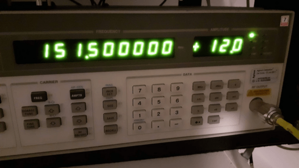
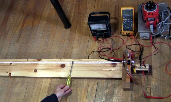
Just how good is it though, does it live up to the promise? [Carol] presents the measurements she took from the device, so you can see for yourselves. She took look at sensitivity, VSWR, and input impedance over a wide range, after first checking its calibration against a GPS-disciplined standard and making a fine adjustment with its on-board trimmer.

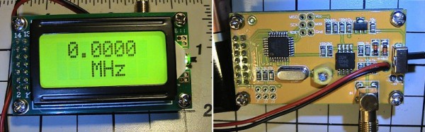
In sensitivity terms it’s a bit deaf, requiring 0.11 Vrms for a lock at 10 MHz. Meanwhile its input impedance decreases from 600 ohms at the bottom of its range to 80 ohms at 200 MHz, with a corresponding shift in VSWR. So it’s never going to match a high-end bench instrument from which you’d expect much more sensitivity and a more stable impedance, but for the price we’re sure that’s something you can all work around. Meanwhile it’s worth noting from the pictures she’s posted that the board has unpopulated space for an SPI interface header, which leaves the potential for it to be used as a logging instrument.

We think it’s worth having as much information as possible about components like this one, both in terms of knowing about new entrants to the market and in knowing their true performance. So if you were curious about those cheap frequency counter modules, now thanks to [Carol] you have some idea of what they can do.

While it’s convenient to buy a counter module like this one, of course there is nothing to stop you building your own. We’ve featured many over the years, this 100MHz one using a 74-series prescaler or this ATtiny offering for example, or how about this very accomplished one with an Android UI?