PIC Based Frequency Counter

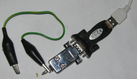
Here’s a PIC based frequency counter that outputs the count via an RS232 serial connection. [Oakkar7] tipped us off about it after seeing the AVR based counter we featured yesterday. This project is a bit older and a bit dirtier.

Inside the metal DB9 housing you’ll find just seven parts. The most important is a PIC 16F628 which handles both the counting and the serial communications. We’re not quite sure how it’s managing to talk to that USB-to-Serial converter without some type of level conversion. Since this microcontroller is not a dedicated counter chip a little bit of trimming must be done to bring the accuracy into spec. There’s also some physical trimming involved. In order to get everything to fit into the small enclosure the circuit was free-formed without a PCB or protoboard and the case of the DIP chip had to be ground down just a bit. As for the readout, a simple script can grab the data and display it in a terminal.

[via Piclist]

Frequency Counter For $10 Worth Of Parts

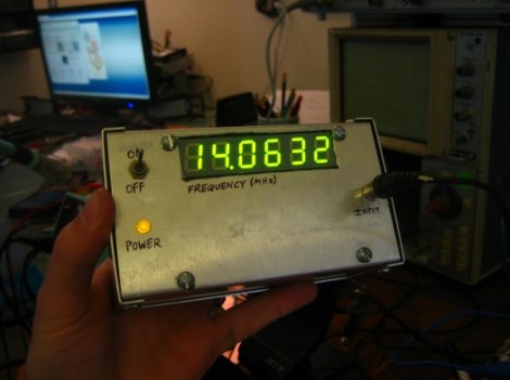
[Scott] built this frequency counter using less than $10 in parts. It’s set up to meter frequencies in megahertz which is fitting since he’s planning to use it with his radio hardware experimentation. But we would find it useful too because our cheap multimeter only reads up to around 4 MHz.

He’s using an ATmega16 that he had on hand but it has features way beyond the specs for the device. He speculates that an ATtiny2313 would easily work in its place. The microcontroller is mostly used to drive the multiplexed 7-segment display after reading the frequency values from the 74LV8154 counter chip that he is using. He doesn’t have a full schematic for the device, but there is a hand drawn diagram for using the frequency counter; the rest should be easy to piece together. Looking at that circuit we don’t think it would be too hard to make this a manual-ranging frequency counter to give you more use out of the dedicated device. Check out [Scott’s] demonstration video which is embedded below the fold.

Continue reading “Frequency Counter For $10 Worth Of Parts”

Nixie Frequency Counter Gone Timepiece

nixie clock hack

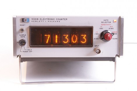
[Windell] of Evil Mad Scientist Laboratories took an ancient Nixie tube based frequency counter and converted it into a clock. The unit he got his hands on is an HP model that was still in great shape. He’s using an internally generated one second pulse as the clock signal, but some modifications are necessary to display time. That’s because the frequency counter is base 10 and clocks use a quirky combination of base 60 and base 12.

It wasn’t too much of a problem to rig up a system to track minutes and seconds. The tens digit for each is monitored by a couple of AND gates that he added to the mix. When they detect a ‘6’ the digit is reset and a pulse increments the next digit as the carry. This is more difficult to accomplish with the hours though. Minutes and seconds count from 0 to 59 but hours don’t start at 0. Instead of over-complicating the logic [Windell] used a bit of slight-of-hand. The Nixie tubes for the hours have been rewired so that when the counter is at 0, the filament in the shape of a 1 lights up. No difference in logic, just a translation that makes them display one digit higher than the actual count.

Simple STM32 Frequency Meter Handles Up To 30MHz With Ease

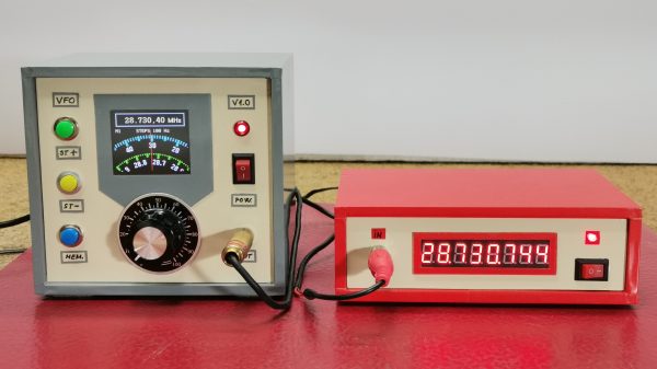
[mircemk] had previously built a frequency counter using an Arduino, with a useful range up to 6 MHz. Now, they’ve implemented a new design on a far more powerful STM32 chip that boosts the measurement range up to a full 30 MHz. That makes it a perfect tool for working with radios in the HF range.

The project is relatively simple to construct, with an STM32F103C6 or C8 development board used as the brains of the operation. It’s paired with old-school LED 7-segment displays for showing the measured frequency. Just one capacitor is used as input circuitry for the microcontroller, which can accept signals from 0.5 to 3V in amplitude. [mircemk] notes that the circuit would be more versatile with a more advanced input circuit to allow it to work with a wider range of signals.

It’s probably not the most accurate frequency counter out there, and you’d probably want to calibrate it using a known-good frequency source once you’ve built it. Regardless, it’s a cheap way to get one on your desk, and a great way to learn about measuring and working with time-varying signals. You might like to take a look at the earlier build from [mircemk] for further inspiration. Video after the break.

Continue reading “Simple STM32 Frequency Meter Handles Up To 30MHz With Ease”

Vintage Digital Frequency Meter Teardown

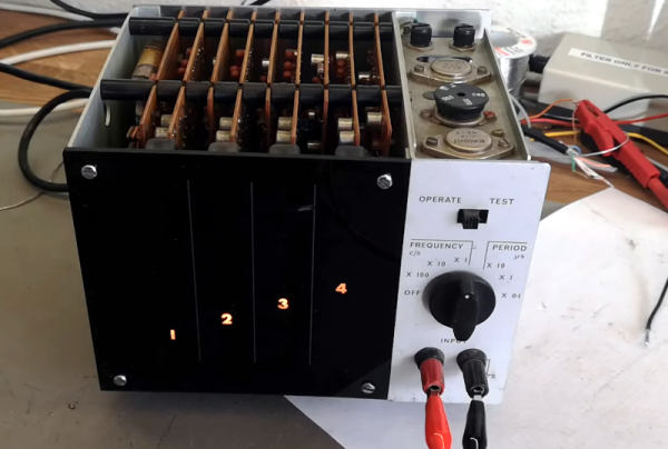
You think of digital displays as modern, but the idea isn’t that new. We had clocks, for example, with wheels and flip digits for years. The Racal frequency counter that [Thomas Scherrer] is playing with in the video below has columns of digits with lamps behind them. You just need the right plastic and ten lightbulbs per digit, and you are in business. Easy enough to accomplish in 1962.

Inside the box was surprising. The stack of PC boards looks more like a minicomputer than a piece of test gear. There were a few novel items inside, too, ranging from a glass-encapsulated crystal to an interesting method of selecting the line voltage.

Continue reading “Vintage Digital Frequency Meter Teardown”

Do Not Attempt Disassembly: Analog Wizardry In A 1960s Counter

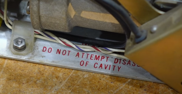
[CuriousMarc] is back with more vintage HP hardware repair. This time it’s the HP 5245L, a digital nixie-display frequency counter from 1963. This unit is old enough to be entirely made of discrete components, but has a real trick up its sleeve, with add-on components pushing the frequency range all the way up to 18 GHz. But this poor machine was in rough shape. There were previous repair attempts, some of which had to be re-fixed with proper components. When it hit [Marc]’s shop, the oscillator was working, as well as the frequency divider, but the device wasn’t counting, and the reference frequencies weren’t testing good at the front of the machine. There were some of the usual suspects, like blown transistors. But things got really interesting when one of the boards had a couple of tarnished transistors, and a handful of nice shiny new ones — but maybe not all the right transistors. Continue reading “Do Not Attempt Disassembly: Analog Wizardry In A 1960s Counter”

To Turn An ATtiny817 Into A 150MHz Counter, First Throw Out The Spec Sheet

One generally reads a data sheet in one of two ways. The first is to take every spec at face value, figuring that the engineers have taken everything into account and presented each number as the absolute limit that will prevent the Magic Smoke from escaping. The other way is to throw out the data sheet and just try whatever you want, figuring that the engineers played it as safely as possible.

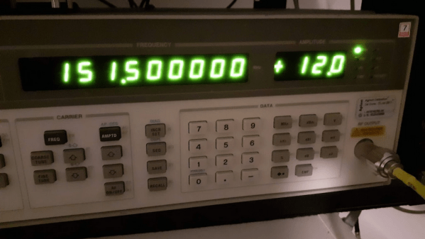
The latter case seems to have been the motivation behind pushing an ATtiny way, WAY beyond what the spec sheet says is possible. According to [SM6VFZ], the specs on the ATtiny817 show that the 12-bit timer/counter D (TCD) should be limited to a measly 32 MHz maximum frequency, above which one is supposed to employ the counter’s internal prescaler. But by using a 10-MHz precision frequency generator as an external clock, [SM6VFZ] found that inputs up to slightly above 151 MHz were countable with 1-Hz precision. Above that point, things started to drift, but that’s still pretty great performance from something cobbled together on an eval board in a decidedly suboptimal way.

We’d imagine this result could lead to some interesting projects, since the undocumented limit for this timer puts it well within range of multiple amateur radio allocations. Even if it doesn’t prove useful, that’s OK — just seeing how far things can be pushed is cool too. And it’s not like this is the first time we’ve caught [SM6VFZ] persuading an ATtiny to do unusual things, either.