TP-Link Debug Protocol Gives Up Keys To Kingdom

If the headline makes today’s hack sound like it was easy, rest assured that it wasn’t. But if you’re interested in embedded device hacking, read on.

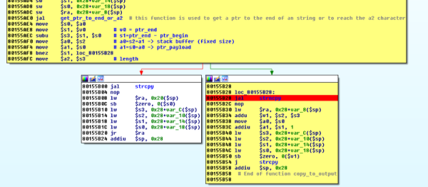
[Andres] wanted to install a custom OS firmware on a cheap home router, so he bought a router known to be reflashable only to find that the newer version of the firmware made that difficult. We’ve all been there. But instead of throwing the device in the closet, [Andres] beat it into submission, discovering a bug in the firmware, exploiting it, and writing it up for the manufacturer.  (And just as we’re going to press: posting the code for the downgrade exploit here.)

This is not a weekend hack — this took a professional many hours of serious labor. But it was made a lot easier because TP-Link left a debugging protocol active, listening on the LAN interface, and not requiring authentication. [Andres] found most of the information he needed in patents, and soon had debugging insight into the running device.

Continue reading “TP-Link Debug Protocol Gives Up Keys To Kingdom”

Reverse Engineering Quadcopter Protocols

Necessity is the mother of invention, but cheap crap from China is the mother of reverse engineering. [Michael] found a very, very cheap toy quadcopter in his local shop, and issued a challenge to himself. He would reverse engineer this quadcopter’s radio protocol. His four-post series of exploits covers finding the right frequency for the radio, figuring out the protocol, and building his own remote for this cheap toy.

[Michael] was already familiar with the capabilities of these cheap toys after reading a Hackaday post, and the 75-page, four language manual cleared a few things up for him. The ‘Quadro-Copter’ operated on 2.4GHz, but did not give any further information. [Michael] didn’t know what channel the toy was receiving on, what data rate, or what the header for the transmission was. SDR would be a good tool for figuring this out, but thanks to Travis Goodspeed, there’s a really neat trick that will put a 2.4GHz nRF24L01+ radio into promiscuous mode, allowing [Michael] to read the transmissions between the transmitter and quadcopter. This code is available on [Michael]’s github.

A needle in an electromagnetic haystack was found and [Michael] could listen in on the quadcopter commands. The next step was interpreting the ones and zeros, and with the help of a small breakout board and soldering directly to the SPI bus on the transmitter, [Michael] was able to do just that. By going through the nRF24 documentation, he was able to suss out the pairing protocol and read the stream of bytes that commanded the quadcopter.

What [Michael] was left with is a series of eight bytes sent in a continuous stream from the transmitter to the toy. These bytes contained the throttle, yaw, pitch, roll, and a ‘flip’ settings, along with three bytes of ‘counters’ that didn’t seem to do anything.  With that info in hand, [Michael] took an Arduino Nano, an nRF04L01+ transceiver, and a Wii nunchuck to build his own transmitter. If you’re looking for a ‘how to reverse engineer’ guide, it generally doesn’t get better than this.

You can check out a video of [Michael] flying his Wiimoted quadcopter below.

Continue reading “Reverse Engineering Quadcopter Protocols”

PJON, Fancy One Wire Arduino Communications Protocol For Home Automation

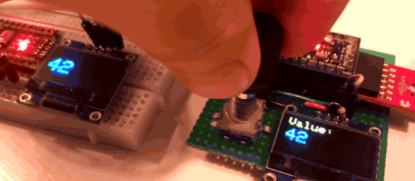
PJON, pronounced like the iridescent sky rats found in every city, is a cool one wire protocol designed by [gioblu].

[gioblu] wasn’t impressed with the complications of I2C. He thought one-wire was too proprietary, too complicated, and its Arduino implementations did not impress. What he really wanted was a protocol that could deal with a ton of noise and a weak signal in his home automation project with the smallest amount of wiring possible.

That’s where is his, “Padded Jittering Operative Network,” comes in. It can support up to 255 Arduinos on one bus and its error handling is apparently good enough that you can hold an Arudino in one hand and see the signals transmitted through your body on the other. The fact that a ground and a signal wire is all you need to run a bus supporting 255 devices and they’ll play nice is pretty cool, even if the bandwidth isn’t the most extreme.

Aside from the cool of DIY protocols. We really enjoyed reading the wiki describing it. Some of the proposed uses was running your home automation through your ducting or water pipes (which should be possible if you’re really good at isolating your grounds). Either way, the protocol is neat and looks fun to use. Or check out PJON_ASK if you want to do away with that pesky single wire.

Shmoocon 2016: Z-Wave Protocol Hacked With SDR

The first talk at 2016 Shmoocon was a great one. Joseph Hall and Ben Ramsey presented their work hacking Z-Wave, a network that has been gaining a huge market share in both consumer and industrial connected devices. EZ-Wave uses commodity Software Defined Radio to exploit Z-Wave networks. This is not limited to sniffing, but also used for control with the potential for mayhem.

Continue reading “Shmoocon 2016: Z-Wave Protocol Hacked With SDR”

Tricking An Ancient Protocol To Play Tunes

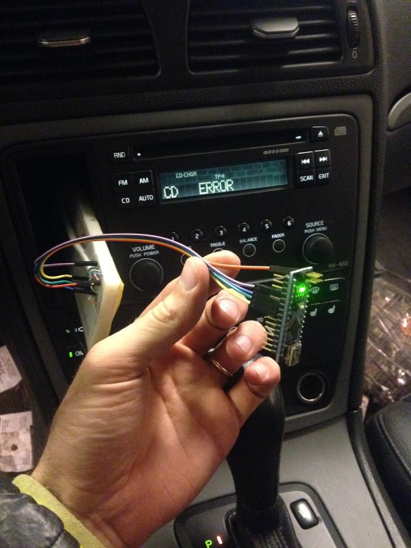
A lot of technological milestones were reached in 2007. The first iPhone, for example, was released that January, and New Horizons passed Jupiter later on that year. But even with all of these amazing achievements, Volvo still wasn’t putting auxiliary inputs on the stereo systems in their cars. They did have antiquated ports in their head units though, and [Kalle] went about engineering this connector to accommodate an auxiliary input.

The connector in question is an 8-pin DIN in the back, which in the days of yore (almost eight years ago) would have been used for a CD changer. Since CDs are old news now, [Kalle] made use of this feature for the hack. The first hurdle was that the CD changer isn’t selectable from the menu unless the head unit confirms that there’s something there. [Kalle] used an Arduino Nano to fool the head unit by simulating the protocol that the CD changer would have used. From there, the left and right audio pins on the same connector were used to connect the auxiliary cable.

If you have a nearly-antique Volvo like [Kalle] that doesn’t have an aux input and you want to try something like this, the source code for the Arduino is available on the project page. Of course, if you don’t have a Volvo, there are many other ways to go about hacking an auxiliary input into various other devices, like an 80s boombox or the ribbon cable on a regular CD player. Things don’t always go smoothly, though, so there are a few nonstandard options as well.

Digging Into The APA102 Serial LED Protocol

[Tim] got his hands on some APA102 RGB LEDs, which are similar in function to the common WS2812 addressable LEDs seen in many projects we’ve featured. The advantage of APA102 LEDs is that they don’t have the strict timing requirements of the WS2812. These LEDs are controlled with a SPI bus that can be clocked at any arbitrary rate, making them easy to use with pretty much any microcontroller or embedded system.

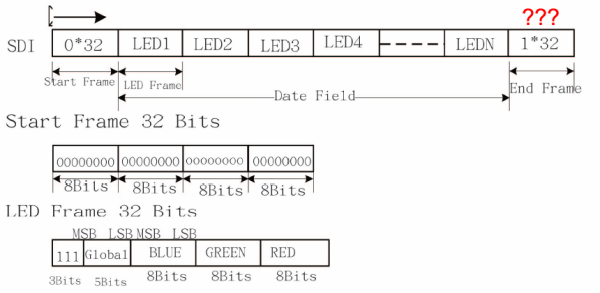
After working with the LEDs, [Tim] discovered that the LEDs function a bit differently than the datasheet led him to believe. [Tim] controlled a strand of APA102 LEDs with an ATtiny85 and connected a logic analyzer between some of the LEDs. He discovered that the clock signal of the SPI interface isn’t just passed through each LED, it actually looks like it’s inverted on the output. After some investigation, [Tim] found that the clock signal is delayed by a half period (which looks like an inversion) before it’s passed to the next LED. This gives the next LED in the strand enough time for data on the data line to become valid before latching it in.

Since the clock is delayed, [Tim] discovered that additional bits must be clocked as an “end frame” to generate clock signals which propagate the remaining data to the end of the strand. Although the datasheet specifies a 32-bit end frame, this only works for strings of up to 64 LEDs. More bits must be added to the end frame for longer strands, which the datasheet doesn’t even mention. Check out [Tim]’s post for more information, where he walks you through his logic analysis of the APA102 LEDs.

Protocol Snooping Digital Audio

More and more clubs are going digital. When you go out to hear a band, they’re plugging into an ADC (analog-to-digital converter) box on stage, and the digitized audio data is transmitted to the mixing console over Ethernet. This saves the venue having to run many audio cables over long distances, but it’s a lot harder to hack on. So [Michael] trained popular network analysis tools on his ProCo Momentum gear to see just what the data looks like.

[Michael]’s writeup of the process is a little sparse, but he name-drops all the components you’d need to get the job done. First, he simply looks at the raw data using Wireshark. Once he figured out how the eight channels were split up, he used the command-line version (tshark) and a standard Unix command-line tool (cut) to pull the data apart. Now he’s got a text representation for eight channels of audio data.

Using xxd to convert the data from text to binary, he then played it using sox to see what it sounded like. No dice, yet. After a bit more trial and error, he realized that the data was unsigned, big-endian integers.  He tried again, and everything sounded good. Success!

While this is not a complete reverse-engineering tutorial like this one, we think that it hits the high points: using a bunch of the right tools and some good hunches to figure out an obscure protocol.