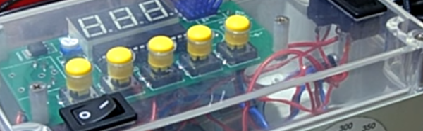
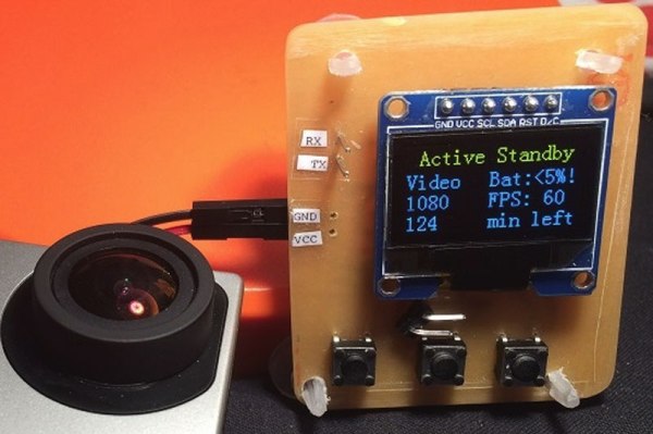
Android-based Reflow Brings Solder Profiles To Your Lab

[Andy Brown] is a prolific hacker and ends up building a lot of hardware. About a year back, he built a reflow oven controller. The board he designed used a large number of surface mount parts. This made it seem like a chicken or egg first problem. So he designed a new, easy to build, Android based reflow controller. The new version uses just one, easy to solder surface mount part. By putting in a cheap bluetooth module on the controller, he was able to write an app which could control the oven using any bluetooth enabled Android phone or tablet.

The single PCB is divided into the high voltage, mains powered section separated from the low power control electronics with cutout slots to take care of creepage issues. A BTA312-600B triac is used to switch the oven (load) on and off. The triac is controlled by a MOC3020M optically isolated triac driver, which in turn is driven by a micro controller via a transistor. The beefy 12Amp T0220 package triac is expected to get hot when switching the 1300W load, and [Andy] works through the math to show how he arrived at the heat sink selection. To ensure safety, he uses an isolated, fully encased step down transformer to provide power to the low voltage, control section. One of his requirements was to detect the zero cross over of the mains waveform. Using this signal allows him to turn on the triac for specific angle which can be varied by the micro controller depending on how much current the load requires. The rectified, but unfiltered ac signal is fed to the base of a transistor, which switches every time its base-emitter voltage threshold is reached.

For temperature measurement, [Andy] was using a type-k thermocouple and a Maxim MAX31855 thermocouple to digital converter. This part caused him quite some grief due to a bad production batch, and he found that out via the eevblog forum – eventually sorted out by ordering a replacement. Bluetooth functions are handled by the popular, and cheap, HC-06 module, which allows easy, automatic pairing. He prototyped the code on an ATmega328P, and then transferred it to an ATmega8 after optimising and whittling it down to under 7.5kb using the gcc optimiser. In order to make the board stand-alone, he also added a header for a cheap, Nokia 5110 display and a rotary encoder selector with switch. This allows local control without requiring an Android device.

Gerbers (zip file) for the board are available from his blog, and the ATmega code and Android app from his Github repo. The BoM list on his blog makes it easy to order out all the parts. In the hour long video after the break, [Andy] walks you through solder tip selection, tips for soldering SMD parts, the whole assembly process for the board and a demo. He then wraps it up by connecting the board to his oven, and showing it in action. He still needs to polish his PID tuning and algorithm, so add in your tips in the comments below.

Continue reading “Android-based Reflow Brings Solder Profiles To Your Lab”

3D Printing on Inflatable Structures

3D Printed Muscle Is Inflated During Printing

Just when you think you’ve seen it all… [Fergal Coulter] over on the RepRap forums just came up with a method of 3D printing on inflatable structures — wait what?

The process uses a custom 3D printer with a paste extrusion head, and a 4th axis — with a pneumatic air supply. Using a spray deposition method, a silicone tube is formed, and then each layer is cured using a infrared light, which is also built into the system. Once the silicone is thick enough, it is then pressurized to inflate through the air-permeable mandrel. A laser then scans the shape of the inflated silicone to allow the computer to generate tool paths for the surface. Then you hit print. Simple right?

Continue reading “3D Printed Muscle Is Inflated During Printing”

Ask Hackaday: Arduino In Consumer Products

Speak with those who consider themselves hardcore engineers and you might hear “Arduinos are for noobs” or some other similar nonsense. These naysayers see the platform as a simplified, overpriced, and over-hyped tool that lets you blink a few LEDs or maybe even read a sensor or two. They might say that Arduino is great for high school projects and EE wannabes tinkering in their garage, but REAL engineering is done with ARM, x86 or PICs. Guess what? There are Arduino compatible boards built around all three of those architectures. Below you can see but three examples in the DUE, Galileo, and Fubarino SD boards.

This attitude towards Arduino exists mainly out of ignorance. So let’s break down a few myths and preconceived biases that might still be lurking amongst some EEs and then talk about Arduino’s ability to move past the makers.

Arduino is NOT the Uno

When some hear “Arduino”, they think of that little blue board that you can plug a 9v battery into and start making stuff. While this is technically true, there’s a lot more to it than that.

  1. An Arduino Uno is just an AVR development board. AVRs are similar to PICs. When someones says “I used a PIC as the main processor”, does that mean they stuck the entire PIC development board into their project? Of course not. It’s the same with Arduino (in most cases), and design is done the same way as with any other microcontroller –
    • Use the development board to make, create and debug.
    • When ready, move the processor to your dedicated board.
  2. What makes an Arduino an “Arduino” and not just an AVR is the bootloader. Thus:
    • An Atmega328P is an AVR processor.
    • An Atmega328P with the Arduino bootloader is an Arduino.
  3. The bootloader allows you to program the AVR with the Arduino IDE. If you remove the bootloader from the AVR, you now have an AVR development board that can be programmed with AVR Studio using your preferred language.

There Is No Special Arduino Language

Arduino "blink" sketch should run on any Arduino compatible board.
Arduino “blink” sketch should run on any Arduino compatible board.

Yes, I know they call them sketches, which is silly. But the fact is it’s just c++. The same c++ you’d use to program your PIC. The bootloader allows the IDE to call functions, making it easy to code and giving Arduino its reputation of being easy to work with. But don’t let the “easy” fool you. They’re real c/c++ functions that get passed to a real c/c++ compiler. In fact, any c/c++ construct will work in the Arduino IDE. With that said – if there is any negative attribute to Arduino, it is the IDE. It’s simple and there is no debugger.

The strength comes in the standardization of the platform. You can adapt the Arduino standard to a board you have made and that adaptation should allow the myriad of libraries for Arduino to work with your new piece of hardware. This is a powerful benefit of the ecosystem. At the same time, this easy of getting things up and running has resulted in a lot of the negative associations discussed previously.

So there you have it. Arduino is no different from any other microcontroller, and is fully capable of being used in consumer products along side PICs, ARMs etc. To say otherwise is foolish.

What is the Virtue of Arduino in Consumer Products?

This is Ask Hackaday so you know there’s a question in the works. What is the virtue of Arduino in consumer products? Most electronics these days have a Device Firmware Upgrade (DFU) mode that allows the end user to upgrade the code, so Arduino doesn’t have a leg up there. One might argue that using Arduino means the code is Open Source and therefore ripe for community improvements but closed-source binaries can still be distributed for the platform. Yet there are many products out there that have managed to unlock the “community multiplier” that comes from releasing the code and inviting improvements.

What do you think the benefits of building consumer goods around Arduino are, what will the future look like, and how will we get there? Leave your thoughts below!

Trick Google Used Hides Secret Messages On LCD Screens

[Travis] didn’t get picked to go to Google I/O this year, but he did have some I/O inspired fun after the fact. His friends who did go told him about specially modified LCD screens Google had scattered around the event. The screens showed normal show information when viewed with the naked eye. When viewed through a special transparent badge included with the I/O swag though, a URL for Google’s scavenger hunt would magically appear. [Travis] was intrigued by the effect, and became hell-bent on reproducing it himself.

[dual-lcd-3Travis] figured out the transparent badge was actually a polarizing filter. Every standard LCD has two of them, usually bonded to the glass of the LCD itself. If you remove the filters from a LCD, you’ll get a prime view of the backlight – unless you’re wearing polarizing glasses of course. Google’s monitors didn’t have that effect though. They showed a full color display, with a second full color hidden display only visible through the polarizer

It only took a bit of three-dimensional thinking for him to figure out Google’s trick. There are actually two LCDs used in the display. The first is a standard LCD with backlight. The trick is to strip the polarizing film off a second LCD and place it in front of the first. The second LCD will be invisible to anyone – without the polarizer.

[Travis] quickly set about replicating the display using several obsolete VGA LCDs. He quickly found that the hard part was peeling the polarizing plastic from the thin glass LCD sandwich. Several LCDs gave up their lives in the effort, but in the end [Travis] was successful. He made everything fit in one case by using a thin LED backlight in a case designed for a monitor with a Cold Cathode Fluorescent Lamp (CCFL).  The result looks exactly like a standard LCD – that is, until viewed through a polarizing filter. Click past the break to see the hidden message LCD in action!

Continue reading “Trick Google Used Hides Secret Messages On LCD Screens”

Controlling Quadcopters With Wireless Mouse Dongles

Last week we gave away a few Crazyflie 2.0 quadcopters to some cool Hackaday Prize entries. This quadcopter ships with the intention of being controlled by your smartphone. But it can also be controlled by a PC with USB dongle and an nRF24LU1+ SOC. [ajlitt] didn’t figure out he wanted the USB dongle (the Crazyradio) that can control this quad until after he used his gift code to claim his Crazyflie quad. No matter; the dongles for Logitech wireless keyboards and mice use the same radio as the Crazyflie and can be modded to make this quad fly.

The board inside the Logitech unifying receiver is a simple affair, with some pads for the USB connector, a crystal, the nRF24LU1+ radio module, and a few passives. To get this radio chip working with his computer, [ajlitt] simply needed to break out the SPI pins and wire everything to a Bus Pirate.

Getting the Crazyradio firmware onto this proved to be a little harder than soldering some magnet wire onto a few pins. The chip was first flashed without a bootloader, a full image with the bootloader was found, after wrangling a single byte into place, [ajlitt] had a working Crazyflie radio made from a wireless mouse dongle. The range isn’t great  – only 30 feet or so, or about as far as you would expect a wireless mouse to work. Excellent work, even if [ajlitt] is temporarily without a mouse.

The Crazyflie 2.0 is available from the Hackaday Store, along with the add-ons if you don’t want to hack your own.

Billy Club Says No

Billy Club Texts Your Mother If You Hit Someone

Mama, just killed hit a man, Put a gun against his head, Pulled my trigger, now he’s dead.
Mama, life had just begun, But now I’ve gone and thrown it all away…

This latest piece of half-art / half-prototype from one of our favorite hacker-artists [vtol] is a billy club equipped with a GSM-module. It automatically sends an SMS to your mother with the text: “Mom, I hit a man.” He calls it the Antenna:

The idea of the project is to create a device which strictly controls the cruelty of police. As all the standard methods of control are ineffective, this project suggests the maternity as the last stronghold of human kindness and responsibility.

An Arduino is equipped with a piezo sensor to detect impact, and a GSM shield takes care of the texting. It’s an interesting concept, similar to requiring police officers to wear body cameras. You can debate the practicality, but we’re always interested in hearing about weapons monitoring tech concepts. One of our favorites has always been the DNA gun from (Judge) Dredd. Did you know there was an Internet Movie Firearms Database? But we digress, check out [vtol’s] demo video:

Continue reading “Billy Club Texts Your Mother If You Hit Someone”

Carbon fiber weaving robot!

Hackaday Prize Entry: Weaving Carbon Fiber With Industrial Robots

Oh to have a 6-axis robot arm to play with… For [Basia Dzaman’s] final graduation project for School of Form, she designed and 3D printed an end effect tool for an industrial KUKA robot — for weaving carbon fiber.

Through an iterative design process, she developed many prototypes of the tool until the one you see above. It’s capable of holding a Dremel multi tool which can be used to drill into a work surface for installing pegs which make up the custom weaving jig. The pegs (nails) are then installed by hand so that the robot can thread carbon fiber — fed through an epoxy bath as it is dispensed — onto the jig. In the example, she shows a traditional Polish handcraft called Snutki (a type of stitching), wrapping the carbon fiber in patterns around the pegs. Once the epoxy cures, a strong structure can be removed.

Remember the 6-axis robot that can 3D print in metal, and is currently working on 3D printing a bridge? [Basia’s] design could do similar things, for a completely different industry. You can check out [Basia]’s video for the project below.

The 2015 Hackaday Prize is sponsored by:

Continue reading “Hackaday Prize Entry: Weaving Carbon Fiber With Industrial Robots”