The Annoying Machine

The Useless Machine – a machine with a toggle switch, a mechanical arm, and something that only exists to turn itself off – is a staple of Instructables and builds from random workbenches the world over. It’s cliché, and now hackaday.io has a better project: The Annoying Machine, a machine that exists purely to annoy.

According to [unigamer], the Annoying Machine is the evil cousin of the Useless Machine. On the outside, it’s extremely simple: a switch labeled ‘on’ and ‘off’, and a hole for an LED. Turn the switch on, and the Annoying Machine will emit an annoying buzzing sound. Switch the Machine off, and the buzzing will go away. Then the switch will flick itself back to on. Insidious.

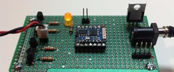
A switch and buzzer is easy enough, but the key component of this build is an actuated rocker switch. It’s basically a normal toggle switch with two additional terminals for a coil that can move the switch back and forth electronically. Throw in an Arduino, buzzer, battery, and a boost converter for the switch, and that’s just about all there is to it.

How to deactivate the Annoying Machine? There’s an accelerometer attached to the Arduino, and by throwing the box up in the air after flicking the switch off, it will reset. There are already plans for a Version 2 of the Annoying Machine that will be even louder and made out of aluminum. Anything to protect it from the inevitable hammers of frustration.

Video below.

Continue reading “The Annoying Machine”

Library Upgrade To PRU Gives Fast IO On Beaglebone

The BeagleBone Black has a powerful featureset: decent clock speed, analog inputs, multiple UART, SPI and I2C channels and on-board memory, to name a few. One missing feature seems to be the lack of support for the two on-board Programmable Real-time Units (PRU’s). Each of these 32-bit processors run independently of the main processor, but are able to interface with the main processor through the use of shared RAM and some interrupts. Unfortunately, PRU’s are not supported and in the absence of information, difficult to program. Enabling the PRU’s will allow them direct access to external sensors via the GPIO pins, for example. Perhaps most enticing is the idea that the PRU’s add real-time processing capability to the BBB.

[Thomas Freiherr] is working on the libpruio project to allow PRU support on the BBB. It is “designed for easy configuration and data handling at high speed. libpruio software runs on the host (ARM) and in parallel on a Programmable Realtime Unit SubSystem (= PRUSS or just PRU) and controls the subsystems”. Additional information about the project is available on the libpruio wiki, and files can be downloaded from here (German Page).

This paper presented at inter.noise2014 (PDF) a couple of months ago has a nice comparison of various small computer/controller boards and outlines the advantages of the BBB once its PRUs are enabled. If readers come across applications of the BBB with PRUs enabled, let us know in the comments. If you want to work your way into the world of the PRU we highly recommend this tutorial series.

Thanks for sending in the tip, [Patrick]

[Image Source: libpruio stepper motor example]

An E-Ink WiFi Connected Display

Wi-Fi Connected E-Ink Display

People implementing the Scrum Methodology for project management often record all their tasks on a big whiteboard. However, it’s useful to have up-to-date graphs to ensure projects are on track. [Sprite_TM] augmented the whiteboard by building an Wi-Fi connected E-Ink Display.

Interfacing with E-Ink displays isn’t easy. A variety of voltages are needed, and the connectors used are tiny. We’ve seen some nice solutions, such as the RePaper display. [Sprite_TM] chose the ED060SC4 display which is available from eBay and has been throughly reverse engineered. A custom breakout board was built up to connect to the tiny FPC pins and generate the required voltages using the LT1945 DC/DC converter.

The next step was adding on Wi-Fi. The ESP12 module was an obvious solution. This module provides Wi-Fi connectivity and a processor capable of controlling the display. The display is powered by a tablet battery, which makes it totally wireless and operates for about 200 days.

A simple laser cut enclosure holds all the bits together, and contains magnets that stick the screen to the whiteboard. On the software side, images are streamed to the ESP12’s processor and loaded directly to the screen, since the ESP12 doesn’t have enough RAM to store an entire screen worth of data. All the firmware can had by cloning a Git repository.

Using MATLAB And SDR To Reverse Engineer 433MHz Messages

Hackers everywhere are having a lot of fun with SDR – as is obvious from the amount of related posts here on Hackaday. And why not, the hardware is cheap and easily available. There are all kinds of software tools you can use to dig in and explore, such as SDR# , Audacity, HDSDR and so on. [illias] has been following SDR projects for a while, which piqued his interest enough for him to start playing with it. He didn’t have any real project in mind so he focused on studying the methodology and the tools available for analyzing 433MHz RF transmission. He describes the process of using MATLAB to recover the transmissions being received by the SDR

He started off by studying the existing tools available to uncover the details of the protocol. The test rig uses an Arduino UNO with the rc-switch library to transmit via a common and inexpensive 433MHz module. SDR# is used to record the transmissions and Audacity allows [illias] to visualize the resulting .wav files. But the really interesting part is where he documents the signal analysis using MATLAB.

He used the RTL-SDR package in conjunction with the Communications System Toolbox to perform spectrum analysis, noise filtering and envelope extraction. MATLAB may not be the easiest to work with, nor the cheapest, but its powerful features and the fact that it can easily read data coming from the SDR makes it an interesting tool. For the full skinny on what this SDR thing is all about, check out Why you should care about Software Defined Radio.

Add a Mic to GPS

Upgraded GPS Now Accepts Voice Commands

[FreddySam] had an old Omnitech GPS which he decided was worthy of being taken apart to see what made it tick. While he was poking around the circuit board he found a couple solder pads labeled as ‘MIC1’. This GPS didn’t have a microphone. So, why would this unit have a mic input unless there is a possibility for accepting voice commands? [FreddySam] was about to find out.

The first step to get the system working was to add a physical microphone. For this project one was scavenged from an old headset. The mini microphone was removed from its housing and soldered to the GPS circuit board via a pair of wires. Just having the mic hanging out of the case would have been unsightly so it was tucked away in an otherwise unfilled portion of the case. A hole drilled in the case lets external sounds be easily picked up by the internalized microphone.

The hardware modification was the easy part. Getting the GPS software to recognize the newly added mic was a bit of a challenge. It turns out that there is only one map version that supports voice recognition, an old version; Navigon 2008 Q3. We suppose the next hack is making this work with new map packs. This project shows how a little motivation and time can quickly and significantly upgrade an otherwise normal piece of hardware. Kudos to [FreddySam] for a job well done.

Hack Your Phone: Turn Your Volume Buttons Into GPIO Ports

Internet connected cameras are mighty useful, specially in situations requiring some form of remote monitoring. An always-on camera that is available over an internet connection, is cheap, and uses re-purposed  hardware – that’s what the Gonzo project hopes to achieve. To accommodate these requirements, the Exploratory Engineering program team in Telenor Digital are using off-the-shelf phone hardware running on top of a fork of Firefox OS. You hang the Gonzo where you want to monitor a situation, after which it will function for up to one month before needing a recharge, sending data to a designated public URL over the 2G network.

A big downside with using such hardware is that it is not designed for the task at hand, and offers no expansion ports that may be needed for certain functions. In this particular case, the designers needed a couple of output ports to drive some LED’s. The hardware guys got a bit creative,  and re-mapped the volume buttons of the phone into generic GPIO ports. On the software side, they looked at where the button GPIO’s were referenced, and located how they are mapped to a keymap. They then added a device driver that maps the GPIO ports to be generic ports instead. Modding the hardware needed a little bit more hard work, figuring out which traces connected to the two volume buttons, adding series resistors, and then wiring the LED’s in place. The project itself is still a work in progress, and you can read more about it at the Gonzo website.

If you’re like one of us and have a box full of old phones lying around, take a look at some creative suggestions here for some Arduino controlled robots.

Thanks for the tip [pb] !

RasPi Garage Door

A Raspberry Pi Garage Door Opener

We can never seem to get enough garage door hacks around here. [Tanner’s] project is the most recent entry into this category. He’s managed to hook up a Raspberry Pi to his garage door opener. This greatly extends his range to… well anywhere with an Internet connection.

His hack is relatively simple. He started with the garage door opener remote. He removed the momentary switch that was normally used to active the door. He bridged the electrical connection to create a circuit that was always closed. This meant that as long as the remote had power, the switch would be activated. Now all [Tanner] had to do was remove the battery and hook up the power connectors to his Raspberry Pi. Since the remote works on 3.3V and draws little current, he is able to power the remote directly from the Pi. The Pi just has to turn its pin high momentarily to activate the remote.

The ability to toggle the state of your garage door from anywhere in the world also comes with paranoia. [Tanner] wanted to be able to tell if the door is up, down, or stopped somewhere in the middle while he was away from home. He also wanted to use as little equipment as possible. Since he already had an IP camera in the garage, he decided to use computer vision to do the detection.

He printed off two large, black shapes onto ordinary white computer paper. One was taped to the top of the door and one to the bottom. A custom script runs on the Pi that grabs the latest image from the camera and uses OpenCV to detect the shapes. If both shapes are visible, then the script can assume the door is closed. Otherwise, it’s likely open. This makes it easier for [Tanner] to know if the door is opened or closed without having to check the camera himself.

Can’t get enough garage door hacks? Try these on for size. Continue reading “A Raspberry Pi Garage Door Opener”