If you need to reverse-engineer a USB protocol on a computer running Linux, your work is easy because you control everything on the target system — you can just look at the raw USB data. If you’d like to reverse-engineer a USB device that plugs into a game console, on the other hand, your work is a lot harder. Until now.
serialusb is a side-project by [Mathieu Laurendeau], alias [Matlo]. His main project, GIMX is aimed at gaming and lets you modify your gaming controller’s performance by passing it first through your PC and tweaking the USB data before forwarding it on to the target console. Want rapid fire? You got it. Alter the steering-wheel sensitivity curves? Sure.
GIMX is essentially a USB man-in-the-middle between your controller and your console, with the added ability to modify the data along the way. For hardware that’s not yet supported by GIMX, though, either [Matlo] would need to borrow your controller, or teach you to man-in-the-middle your own USB traffic. And that’s what serialusb does.
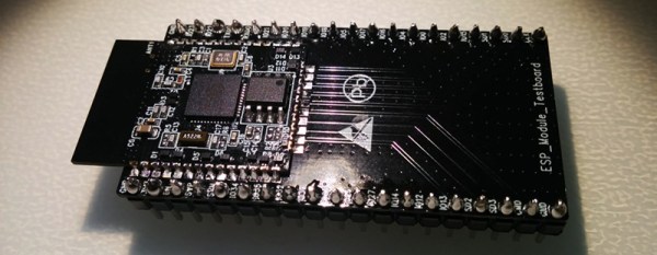
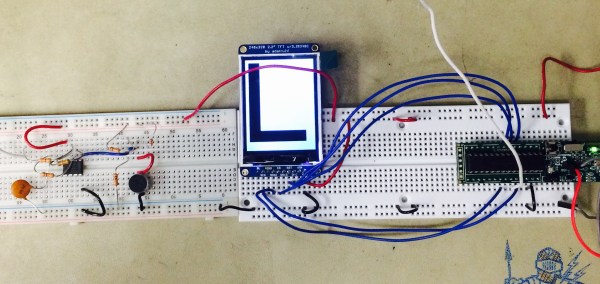
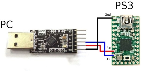
The hardware required is very modest: a USB-to-serial adapter and an ATmega32u4-based Arduino clone. Many of you could whip this together with parts on hand, and it’s the same hardware you’d need to run GIMX anyway. Data goes through your computer, is usbmon’ed and wireshark’ed, and then passed over serial to the ATmega which then converts it back into USB, plugged into the console. A very tidy little setup.
In case this seems familiar, we’ve covered a similar trick by [Matlo] before that used a BeagleBoard as the computer in the middle. That’s a sweet setup for sure, but if you don’t have a spare single-board computer lying around, now you can get it done for only around $5 in parts. Happy USB reversing!