I still remember the first time I saw a satellite, I was 12 years old and was camping far away from the city lights. As I gazed up at the night sky, I could actually track satellites with my naked eye as they zoomed across the night’s sky. It was amazing. Nowadays, it’s getting harder to spot relatively small satellites with light pollution from large cities.
The International Space Station (ISS) on the other hand is a large piece of hardware — it’s about the size of a football field, and according to NASA it’s the second brightest object in the night sky. So why don’t we see it more often? Well, part of the reason is that you don’t know where to look. [Grady Hillhouse] set out to change that by building a what is basically a 2 degrees of freedom robot arm that will point you to where the ISS is at any given moment.
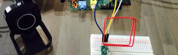
[Grady] uses a stepper motor for the azimuth, and a standard servo for the elevation, all powered by an Nucleo F401 development board, and an Adafruit motor shield and slip ring. The structure is made using some Erector set like parts from Actobotics.
He wrote the code from this open source project here. He’s currently cleaning up his code, and says he’ll be posting it up shortly. In the mean time, you can watch a video detailing the build in the video after the break. Or if you can’t wait, you can visit NASA’s web site to receive email or SMS messages on when the ISS is view-able in your hood.
Continue reading “It’s 10 PM, Do You Know Where Your Space Station Is At?”