Making A DIY Refrigerated Vest With Battery And Solar Power

Keeping a cool head is difficult at the best of times, least of all when it’s summer and merely thinking of touching bare skin to the pavement already gets you a second-degree burn. Unfortunately, it’s not possible to spend all summer in an air-conditioned room, but what if you took said room with you? Introducing [Hyperspace Pirate]’s air-conditioned vest.

Following on from last time’s adventures with a battery-powered air-conditioner that merely blew cold air onto one’s overheating body, this time the same compressor is used for a more compact build.

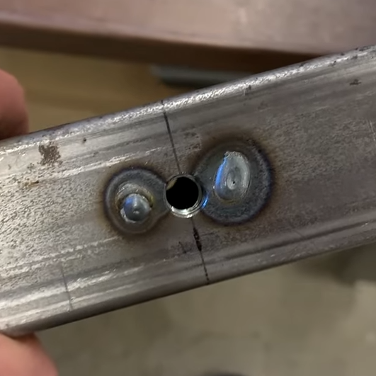
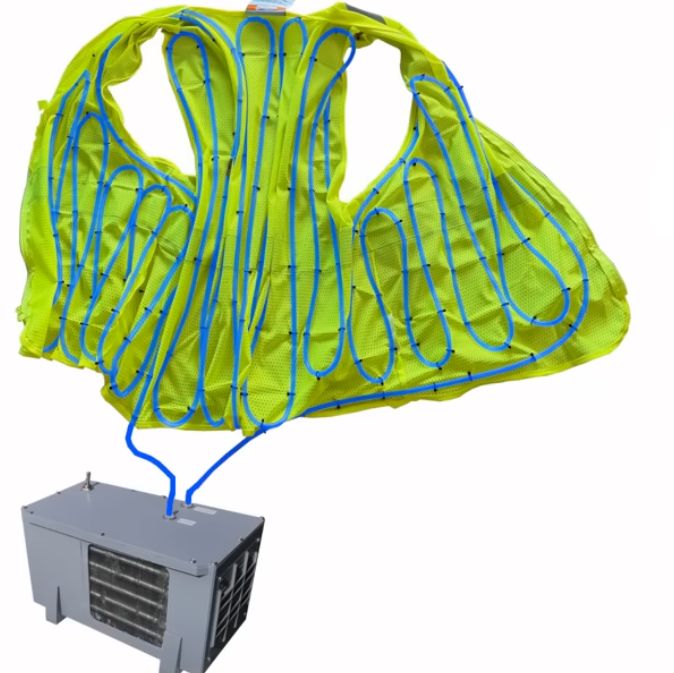
Since obviously using your body as part of the evaporator would be uncomfortable, instead a heat exchanger was used that transfers the delicious frosty cold to water-filled tubing, zip-tied inside a very fashionable vest.

The basic unit runs on a couple of LiPo packs, but a solar-powered circuit was also built and tested using two small-ish panels. Of course, the requisite backpack-sized setup for that configuration is somewhat bulky, but at least the panels can also provide shade in addition to power for the compressor, hitting two fiery birds with one frosty stone.

Compared to one of those solar-powered caps with a built-in fan, this unit with some refinement could actually be an improvement, as well as keeping you a lot chillier. We’re looking forward to [Hyperspace]’s trial runs in the upcoming Floridian summer, as well as future chilling adventures.

Continue reading “Making A DIY Refrigerated Vest With Battery And Solar Power”

He’s A Wrapper (Wire Wrapper, That Is)

Before PCBs, wiring electronic circuits was a major challenge in electronics production. A skilled person could make beautiful wire connections between terminal strips and components with a soldering iron, but it was labor-intensive and expensive. One answer that was very popular was wire wrapping, and [Sawdust & Circuits] shows off an old-fashioned wire wrap gun in the video below.

The idea was to use a spinning tool to tightly wrap solid wire on square pins. A proper wrap was a stable alternative to soldering. It required less skill, no heat, and was easy to unwrap (using a different tool) if you changed your mind. The tech started out as wiring telephone switchboards but quickly spread.

Not all tools were guns or electric. Some used a mechanical handle, and others were like pencils — you simply rotated them by hand. You could specify levels for sockets and terminals to get a certain pin length. A three-level pin could accept three wire wrap connections on a single pin, for example. There were also automated machines that could mass-produce wire-wrapped circuits.

The wire often had thin insulation, and tools usually had a slot made to strip the insulation on the tiny wires. Some guns created a “modified wrap” that left insulation at the top one or two wraps to relieve stress on the wire as it exited the post. If you can find the right tools, wires, and sockets, this is still a viable way to make circuits.

Want to know more about wire wrapping? Ask [Bil Herd].

Continue reading “He’s A Wrapper (Wire Wrapper, That Is)”

Why PlayStation Graphics Wobble, Flicker And Twitch

Although often tossed together into a singular ‘retro game’ aesthetic, the first game consoles that focused on 3D graphics like the Nintendo 64 and Sony PlayStation featured very distinct visuals that make these different systems easy to distinguish. Yet whereas the N64 mostly suffered from a small texture buffer, the PS’s weak graphics hardware necessitated compromises that led to the highly defining jittery and wobbly PlayStation graphics.

These weaknesses of the PlayStation and their results are explored by [LorD of Nerds] in a recent video. Make sure to toggle on subtitles if you do not speak German.

It could be argued that the PlayStation didn’t have a 3D graphics chip at all, just a video chip that could blit primitives and sprites to the framebuffer. This forced PS developers to draw 3D graphics without such niceties like a Z-buffer, putting a lot of extra work on the CPU.

Continue reading “Why PlayStation Graphics Wobble, Flicker And Twitch”

Welding Nuts Inside Metal Tubes, Painlessly

[Jer Schmidt] needed a way to put a lot of M8 bolts into a piece of square steel tubing, but just drilling and tapping threads into the thin steel wouldn’t be strong enough. So he figured out a way to reliably weld nuts to the inside of the tube, and his technique works even if the tube is long and the inside isn’t accessible.

Two smaller holes on either side. Weld through the holes. A little grinding results in a smooth top surface.

Essentially, one drills a hole for the bolt, plus two smaller holes on either side. Then one welds the nut to the tubing through those small holes, in a sort of plug weld. A little grinding is all it takes to smooth out the surface, and one is left with a strong threaded hole in a thin-walled tube, using little more than hardware store fasteners.

The technique doesn’t require access to the inside of the tube for the welding part, although getting the nut back there in the first place does require a simple helper tool the nut can slot into. [Jer] makes one with some scrap wood and a table saw, just to show it doesn’t need to be anything fancy.

Another way to put a threaded hole into thin material is to use a rivnut, or rivet nut (sometimes also used to put durable threads into 3D prints) but welding a plain old nut to the inside was far more aligned with what [Jer] needed, and doesn’t rely on any specialty parts or tools.

[Jer]’s upcoming project requires a lot of bolts all the way down long tubing, which is what got him into all of this. Watch it in action in the video below, because [Jer] has definitely worked out the kinks, and he steps through a lot of tips and tricks to make the process painless.

Thanks [paulvdh] for the tip!

Continue reading “Welding Nuts Inside Metal Tubes, Painlessly”

Driving Sim Handbrake Based On Load Cell

Simulator-style video games are designed to scale in complexity, allowing players to engage at anything from a casual level to highly detailed, realistic simulation. Microsoft Flight Simulator, for example, can be played with a keyboard and mouse, a controller, or a huge, expensive simulator designed to replicate a specific airplane in every detail. Driving simulators are similar, and [CNCDan] has been hard at work on his DIY immersive driving sim rig, with this hand brake as his latest addition.

For this build, [CNCDan] is going with a lever-style handbrake which is common in motorsports like drifting and rallying. He has already built a set of custom pedals, so this design borrows heavily from them. That means that the sensor is a load cell, which takes input force from a lever connected to it with a spring mechanism. The signal is sent to an Arduino for processing, which is set up to send data over USB like any joystick or controller. In this case, he’s using an Arduino that was already handling inputs from his custom shifter, so he only needed to use another input and add some code to get his handbrake added into his sim.

[CNCDan] built a version of this out of laser-cut metal parts, but also has a fully 3D printable one available as well. Plenty of his other videos about his driving rig are available as well, from the pedal assembly we mentioned earlier to the force-feedback steering wheel. It’s an impressive set of hardware with a feel that replicates racing about as faithfully as a simulator could. Interestingly, we’ve also seen this process in reverse as well where a real car was used instead as a video game controller.

Continue reading “Driving Sim Handbrake Based On Load Cell”

Getting The VIC-20 To Speak Again

The Commodore Amiga was famous for its characteristic Say voice, with its robotic enunciation being somewhat emblematic of the 16-bit era. The Commodore VIC-20 had no such capability out of the box, but [Mike] was able to get one talking with a little bit of work.

The project centers around the Adventureland cartridge, created by Scott Adams (but not the one you’re thinking of). It was a simple game that was able to deliver speech with the aid of the Votrax Type and Talk speech synthesizer box. Those aren’t exactly easy to come by, so [Mike] set about creating a modern equivalent. The concept was simple enough. An Arduino would be used to act as a go between the VIC-20’s slow serial port operating at 300 bps and the Speakjet and TTS256 chips which both preferred to talk at 9600 bps. The audio output of the Speakjet is then passed to an LM386 op-amp, set up as an amplifier to drive a small speaker. The lashed-together TTS system basically just reads out the text from the Adventureland game in an incredibly robotic voice. It’s relatively hard to understand and has poor cadence, but it does work – in much the same way as the original Type and Talk setup would have back in the day!

Text to speech tools have come a long way since the 1980s, particularly when it comes to sounding more natural. Video after the break.

Continue reading “Getting The VIC-20 To Speak Again”

A graph of current versus time for circuits with and without inductors

A Deep Dive Into Inductors

[Prof MAD] runs us through The Hidden Power of Inductors — Why Coils Resist Change.

The less often used of the passive components, the humble and mysterious inductor is the subject of this video. The essence of inductance is a conductor’s tendency to resist changes in current. When the current is steady it is invisible, but when current changes an inductor pushes back. The good old waterwheel analogy is given to explain what an inductor’s effect is like.

There are three things to notice about the effect of an inductor: increases in current are delayed, decreases in current are delayed, and when there is no change in current there is no noticeable effect. The inductor doesn’t resist current flow, but it does resist changes in current flow. This resistive effect only occurs when current is changing, and it is known as “inductive reactance”.

After explaining an inductor’s behavior the video digs into how a typical inductor coil actually achieves this. The basic idea is that the inductor stores energy in a magnetic field, and it takes some time to charge up or discharge this field, accounting for the delay in current that is seen.

There’s a warning about high voltages which can be seen when power to an inductor is suddenly cut off. Typically a circuit will include snubber circuits or flyback diodes to help manage such effects which can otherwise damage components or lead to electric shock.

[Prof MAD] spends the rest of the video with some math that explains how voltage across an inductor is proportional to the rate of change of current over time (the first derivative of current against time). The inductance can then be defined as a constant of proportionality (L). This is the voltage that appears across a coil when current changes by 1 ampere per second, opposing the change. The unit is the volt-second-per-ampere (VsA-1) which is known as the Henry, named in honor of the American physicist Joseph Henry.

Inductance can sometimes be put to good use in circuits, but just as often it is unwanted parasitic induction whose effects need to be mitigated, for more info see: Inductance In PCB Layout: The Good, The Bad, And The Fugly.

Continue reading “A Deep Dive Into Inductors”