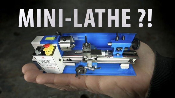
[This Old Tony] is no stranger to quality tools, but he started on a mini lathe. Nostalgia does not stop him from broadcasting his usual brand of snark (actually, it is doubtful that anything short of YouTube going offline will stop that). He rates the lathe’s ability to machine different materials and lets you decide if this is an investment, or a money pit.
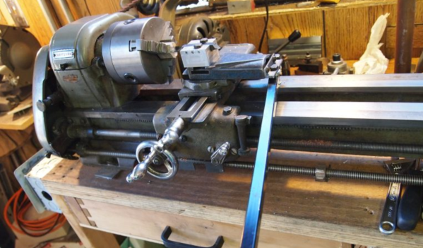
Lathe parts range from a chintzy start/stop button assembly that looks like it would be at home on a Power Wheels restoration project to a convenient cam locking mechanism on the tail stock which is an improvement on the lathe with which our narrator learned. We see the speed tested and promptly disproved as marketing hoopla unless you allow for a 40% margin of error. It uses a 500 watt DC motor, so don’t try correcting for mains power frequency differences. The verdict on the lead screw and thread dial is that you get what you pay for and this is demonstrated by painstakingly cutting threads into aluminum. Finally, we see torture tests on cold rolled steel.
Maybe someone from the mini lathe community will stop by with their two-cents. If you appreciate this introduction to lathes, consider [This Old Tony]’s guide to CNC machines or injection molding. But for us, [Quinn Dunki’s] series of machine tools has been a real treat this year.