Guitar Becomes An Improved Color Organ

[Charles] wanted to put some LEDs in his guitar. He also wanted individual notes to output certain colors, but he couldn’t find any projects with tone-based algorithms to convert sound into colors. After about a year of work, his ColorChord guitar was born.

Unlike every other color organ build we’ve seen, the color of a note does not relate to the absolute pitch of the note. Instead, the colors are mapped within a musical key. A I chord will always be Yellow, a IV chord will always be purple, and a V chord will always be blue. Playing in the key of C will have the LEDs output yellow, purple, and blue for a C, F and G chord, respectively.
Continue reading “Guitar Becomes An Improved Color Organ”

All About Accelerometers

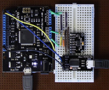
If you’ve ever wondered about the use of or theory behind or the use of accelerometers, this tutorial by Love Electronics is a very good resource. In this article, Love takes one through how to hook up an ADXL345 accelerometer and use it with a Netduino processor. Before the subject of hooking everything up is broached, a very good discussion is given on the general theory and operation of accelerometers.

Information is given about installing all the required software and libraries. Additionally, a mini tutorial about writing a “hello” application using the .NET framework is given. Finally, the application gives the [Windows Presentation Foundation] tools necessary to visualize the raw data that the Netduino produces.

One could really start using this processor and accelerometer from scratch with this tutorial and some basic electronics knowledge.  This could add a great new feature to your next robot or allow measurement that couldn’t be done with simpler sensors.

Using An Arduino To Measure Inductance

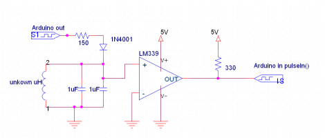
Measuring an inductor is not something that most multi-meters can do. You usually need a high precision resistor (1% or better) in series with the inductor, a function generator to put a signal through the circuit, and an oscilloscope to measure the result. But what can you do if you don’t have these tools on hand? [Andrew Moser] has a method that lets you pull it off with an Arduino and an LM339 quad comparator.

The circuit works by feeding a signal in from the Arduino. This waveform is affected by the LC circuit, filtered by the comparator chip, then read back out the other side by the Arduino. That resulting signal is a square wave, which is an easy target for the Arduino to measure. That timing measured from the square wave can then be used to calculate the inductor’s value.

This is quite handy if you’re winding your own inductors. Now you can precisely tune that Joule Thief you’ve been working on.

[via Dangerous Prototypes and Adafruit]

Creating Music From GPU Noise

Yep, that’s a picture of a Laptop rocking out on an electric guitar. In what can only be described as a truly bizarre hack [CNLohr] discovered that the RF noise from the computer can be used to play music through the guitar’s pickup.

Check out the clip after the break to hear an annoying, but very discernible rendition of Jingle Bells. Once [CNLohr] stumbled onto the fact that changes in what the graphic processing unit is doing was affecting the pitch detected by the pickup he started writing some code. Now he’s got a program that automatically calculates the size of the window, and produces a white square on a black background to dial in the GPU at the right frequencies.

He mentions in the notes accompanying his video that he had to turn off Vsync to get this to work right. We don’t understand why but we’d love to hear what you think in the comments.

Continue reading “Creating Music From GPU Noise”

Cypherbot Uses Older UC And Retro-controller

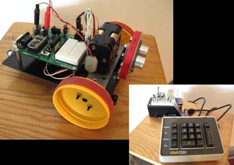
[PJ Allen] has been working on a little robot which he calls Cypherbot. The control circuitry is quite familiar; a Board of Education which features the Basic Stamp 2 microcontroller. This is an older and slower microprocessor, but it works quite well for this application since there’s no need for speed or heavy number crunching. The wheels of the bot are made out of plastic lids (we’re thinking peanut butter jars) with rubber bands for traction that are each driven by a servo motor. The third wheel is tiny and swivels as needed.

The front of the bot has a PING ultrasonic sensor mounted on a servo motor which lets the bot scan back and forth for a wider obstacle avoidance angle. In addition to the autonomous mode there’s an Xbee remote control. [PJ] picked up an Atari keyboard and is using that as the user input. Check out the little guy driving around the house in the video after the break.

Continue reading “Cypherbot Uses Older UC And Retro-controller”

The Firebird32, A New Dev Board On The Block

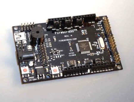
Here is yet another development board to add to your list (If you are into keeping lists), introducing the Firebird32. There seems to be no end to the production of new development boards, following the current style the Firebird32 comes in the familiar Arduino form factor to fit all of your Arduino shields.

The Firebird32 from [Wytec] is build around the 32bit Freescale Flexis MCU [MCF51JM128] running the Coldfire V1 core commonly found in industrial and medical equipment. We were kindly donated a board before release, the first thing that we noticed was  the onboard 8×2 segment LCD which makes the perfect debuging tool. The board along with fitting standard Arduino shields has extra input headers for a keypad, an accelerometer and an extra communication header (IC2/SPI/SCI). It’s also sporting 8 x 12bit analogue inputs, external 32k EEPROM, an RGB LED, a buzzer and an extra push button. The Flexis chip along with the beefy 32bit processor can run at a clock rate up to 48Mhz using PLL and has an integrated USB port, all of this for under $30.

Continue reading “The Firebird32, A New Dev Board On The Block”

Frustrating Fun With Magnetic Levitation

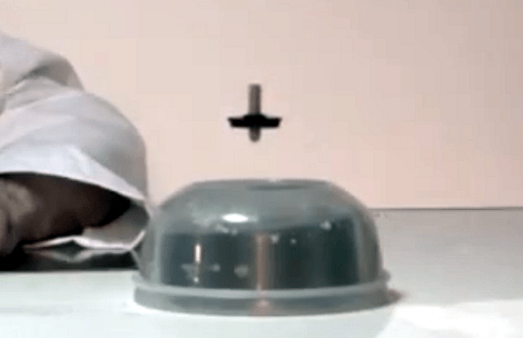
[Andrey Mikhalchuk] built his own magnetic levitation device and you can too… if you have the patience. He’s not using electromagnets, like the Arduino levitator or the floating globe. Instead, a pair of ceramic ring magnets and a few hours are all it takes.

The base of his device is a couple of very large ring magnets that would most often be used in speakers. It’s hard to see them in the image above because there’s an inverted plastic container obscuring them. A second (or third depending on how you’re counting) ring magnet is selected because it is smaller than the circular void in the magnetic base. It’s impossible to simply balance the magnet in the air, but spinning it is a different story. By creating a perfectly balance magnetic top, then spinning it inside the magnetic field of the base, you can leave it floating in mid-air.

Check out the video after the break. It’s a neat effect, but you really do have to have a perfect setup for it to work. [Andrey] mentions that it takes a couple of hours to fine-tune. And if the ambient conditions change slightly, it throws the whole thing off.

Continue reading “Frustrating Fun With Magnetic Levitation”