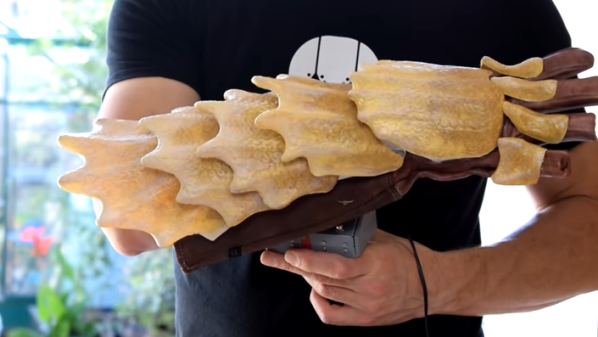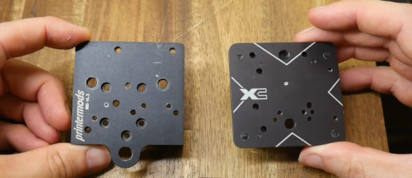
[Teaching Tech] has been interested in adding a tool changer to his 3D printer. E3D offers a system that allows you to switch print heads or even change out a hot end for a laser or a (probably) light-duty CNC head. The price of the entire device, though, is about $2,500, which put him off. But now he’s excited about a product from PrinterMods called XChange. This is a kit that will allow rapid tool changes on many existing printers and costs quite a bit less. Preorder on KickStarter is about $150, but that probably won’t be the final price.
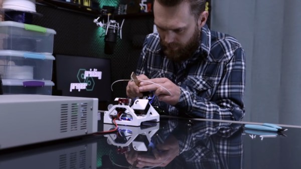
Not all printers are compatible. It appears the unit attaches to printers that have linear rails and there is an adapter for printers that have V rollers in extrusions. Supposedly, there is an adapter in the works for printers that use rods and bearings.
Continue reading “XChange Promises Inexpensive Tool Changes For 3D Printers”