Streamline Your SMD Assembly Process With 3D-Printed Jigs

Your brand-new PCBs just showed up, and this time you even remembered to order a stencil. You lay the stencil on one of the boards, hold it down with one hand, and use the other to wipe some solder paste across…. and the stencil shifts, making a mess and smearing paste across the board. Wash, rinse (with some IPA, of course), repeat, and hope it’ll work better on the next try.

openscad window
A PCB jig generated by OpenSCAD

Maybe it’s time to try Stencilframer, a 3D-printable jig generator created by [Igor]. This incredibly useful tool takes either a set of gerbers or a KiCad PCB file and generates 3D models of a jig and a frame to securely hold the board and associated stencil. The tool itself is a Python script that uses OpenSCAD for all 3D geometry generation. From there, it’s a simple matter to throw the jig and frame models on a 3D printer and voilĂ !– perfectly-aligned stencils, every time.

This is a seriously brilliant script. Anyone whose gone through the frustration of trying to align a stencil by hand should be jumping at the opportunity to try this out on their next build. It could even be paired with an Open Reflow hot plate for a fully open-source PCB assembly workflow.

Continue reading “Streamline Your SMD Assembly Process With 3D-Printed Jigs”

This $0 Filament Drybox Needs Nearly No Parts

All 3D printer filament benefits from being kept as dry as possible, but some are more sensitive to humidity than others. The best solution is a drybox; a sealed filament container, usually with some desiccant inside. But in a pinch, [Spacefan]’s quick and dirty $0 drybox solution is at least inspiring in terms of simplicity.

The only added part is this 3D-printed fitting.

[Spacefan]’s solution uses a filament roll’s own packing materials and a single 3D-printed part to create a sealed environment for a single roll. The roll lives inside a plastic bag (potentially the same one it was sealed in) and filament exits through a small hole and 3D-printed fitting that also uses a bit of spare PTFE tubing. The box doubles as a convenient container for it all. It doesn’t have as much to offer as this other DIY drybox solution, but sure is simple.

While we appreciate the idea, this design is sure to put a lot of friction on the spool itself. It will be a lot of extra work to pull filament off the spool, which needs to turn inside a bag, inside a box, and that extra work will be done by the 3D printer’s extruder, a part that should ideally be working as little as possible. The re-use of materials is a great idea, but it does look to us like the idea could use some improvement.

What do you think? Useful in a pinch, or needs changes? Would adding a spindle to support the spool help? Let us know what you think in the comments.

A functioning model of the Wunderwaffe DG-2 from Call of Duty: Zombies.

DIY Wunderwaffe And Others Make Up This Open-Source Arsenal

Unless you stay up all night and have a dozen printers going, it’s probably way too late to make one of these beautiful prop weapons designed by [Andrew] of The Ray Gun Project in time for Halloween. Most of them are from Call of Duty: Zombies, though there is an awesome little disco grenade from Fortnite as well.

All of the projects are fantastic, but we chose to highlight the Wunderwaffe DG-2 from COD: Zombies because, well, vacuum tubes. For those unfamiliar with the ‘waffe’s operation, those vacuum tubes act as ammo magazines. Once they’re empty, you power them down with that big red switch and eject them one at a time with the lever, just like in the game.

Inside is a Feather M0 Express that runs the RGB LEDs and uses a Hall effect sensor to read magnets in the quick-change ammo magazine. You can see how it works in the demo video after the break.

There are BOMs for several of the prop weapons, along with assembly drawings and support forums for anyone who wants to build their own. Don’t feel like gathering all the bits and bobs yourself? [Andrew] is selling hardware packs for the ray gun, but you’ll have to scrounge the parts yourself if you want to build the Wunderwaffle.

Are you a Grinch who wants to keep kids off of your lawn? Scare ’em off with a giant NERF gun.

Continue reading “DIY Wunderwaffe And Others Make Up This Open-Source Arsenal”

Simplify 3D Printer Wiring With CAN Bus

[mark] had an interesting idea when looking at all the wiring of a typical 3D printer; Use CAN Bus. There are a lot of wires going to the extruder assembly, and with most designs this thing is flying around at quite some speed. You’ve got connections for powering the heater, fan power, four wires for the extruder motor, thermistor sensor wires. You get the idea. Lots of wires. Worse, they’re all moving around with the axis, and if failures occur at either end due to poor strain relief, or the conductors themselves break, then all manner of interesting failures can occur. If the hot end thermistor connection goes open circuit, usually no damage occurs but the temperature control goes out the window and your print will fail.

Now if you push the electronics needed to drive and control the extruder, directly onto the moving body itself, and hook-up to the main printer electronics with CAN Bus, you can do the whole moving interconnect thing with a measly four wires. Yes, you need another PCB assembly, so it adds cost, but it does also simply the electronics at the control end, so some savings can be made. [mark] has used CAN Bus due its availability with modern microcontrollers and also its designed-in robustness, thanks to its automotive and industrial heritage. When you think about it, this is a rather obvious thing to do, and we’re not sure why we’ve not see it much before.

If you want to dig into the detail, the project GitHub has the schematics and code ready to go.


Continue reading “Simplify 3D Printer Wiring With CAN Bus”

Handwriting Robots Are Sending Snail Mail

As a kid, you might remember taking a whole fistful of markers or crayons, gently lining them all up for maximum contact, mashing them into the paper, and marveling at the colorful multitude of lines. It seemed like an easy way to write many times more things with less effort. While not quite the same idea but in a similar vein, [Aaron Francis] shared an experience of creating handwriting robots to write thousands of letters.

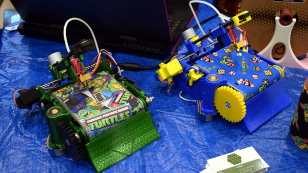
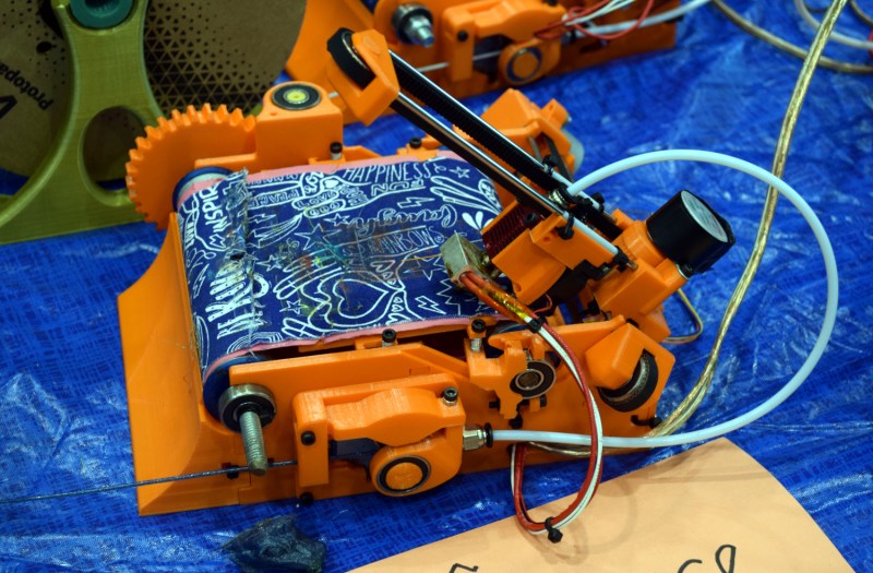
Why did [Aaron] need to write thousands of letters? Direct mailing, of course! If you were sending someone a letter, if it looked handwritten they’re much more likely to open it. What better way to make it look handwritten than to use a pen rather than a printer? They started off with Axidraw, a simple plotter made by EMSL. Old laptops controlled a few plotters and they started to make progress. As with most things, scale became tricky. Adding more plotters just means more paper to replace and machines to restart. An automated system of replacing paper is fiendishly difficult so they went for a batching system. A sheet of plywood that can hold dozens of sheets of paper became the basis of a new mega-plotter. 3D printers and laser cutters helped make adapters and homing teeth. A Raspberry Pi replaced the old laptops and they scaled up to a few machines.

All in all, a pretty impressive build. If you’re looking to dip your toes into the plotting water, this pen plotter is about as simple as you can get.

Copper tubes formed by 3D printed press dies

Can 3D Printed Press Tools Produce Repeatable Parts?

When we think of using a press to form metal we think of large stamps with custom made metal dies under unimaginable hydraulic pressure. It’s unlikely we’d e think of anything 3D printed. And in a commercial environment we’d be right. But your average garage hacker is far more likely to have access to a bench vise and a 3D printer. It’s in this context that [The Shipping Container Garage] has spent considerable time, effort, and money perfecting a process for pressing copper parts with 3D printed dies, which you can watch below the break.

In the quest to make a custom intake manifold for his project car, [The Shipping Container Garage] first made 3D printed jigs for cutting out a manifold flange that bolts to the cylinder head. It’s a process he calls Analog CNC, as all the cutting is done by hand.

Buoyed by his success, he proceeded with the next step: making manifold runners. His metal of choice was copper. While softer than many metals such as steel, he found it too hard. In the video, he describes his method for annealing the copper. Once cooled, two 3D printed dies are pressed into the copper tubes to progressively shape them. Watch the video to find out one of the neatest details of the die itself: how he gets it out!

Of course no matter how clever this all is, it’s useless if it produces poor results. And that’s where the most astounding part of the build is: The parts are all the same within 0.006 inches (0.15mm) of each other, and the parts fit the manifold flange they were made for. Additionally, the die can be used for the duration of the project at hand. For low volume production, this appears to be a viable method. It’ll be interesting to see what others do to iterate these processes to even more advanced stages.

You may also like to see 3D printing used in leather working and in jigs for beautiful circuit sculptures. A big thanks to [JapanFan] for the tip! If you have your own pressing hacks to share, let us know via the Tip Line!

Continue reading “Can 3D Printed Press Tools Produce Repeatable Parts?”

3D Printer Bed Probing Using A Tact Switch And Coin Cell

Inspired by his CNC’s leveling system, [Chuck] built a small PCB to help level his 3D printer and he shares the details in the video you can see below. The idea is simple, the nozzle pushes down on the PCB which has a tact switch underneath. When the switch closes, an LED lights.

In practice, you measure the height of the board and use that for your Z offset, and you are done. Our only concern would be how repeatable the switch is. Granted, most people use a piece of paper and that’s probably not totally repeatable or accurate either. Proper feeler gauges are the “right” way to do it, but we know only a few people who do that.

If you ever look into the repeatability of various Z probes like the proximity sensors or the little pins that drop out of a 3D Touch probe, they aren’t that repeatable. Some people use microswitches, too, which is pretty similar to this approach and is apparently good enough.

The board is available, but it is simple enough that you could create it — or an equivalent — with just about any method you use for your PCBs. [Chuck’s] prototype board was milled. We are always surprised more people don’t use the nozzle itself to sense the bed. Some people go to a lot more trouble than just electrical contact even for CNC.

Continue reading “3D Printer Bed Probing Using A Tact Switch And Coin Cell”