Proper Cassettes For Your FPGA Retrocomputer

You can tell the age of someone in our community with a simple question: what were the first removable data storage media you used? Punched cards for the venerable, cassettes for the middle-aged, floppies for the thirtysomethings, Flash cards for the twentysomethings, and maybe even “What’s a removable storage medium?” for the kids brought up on cloud services.  Even with refreshed interest in retrocomputing the cassette hasn’t made a comeback, but maybe that owes something to the hardware. Createing a cassette interface for an FPGA is a task that’s often overlooked, and that’s a project [zpekic] has tackled.

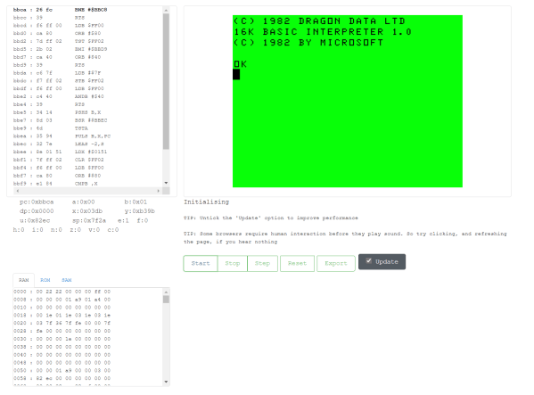
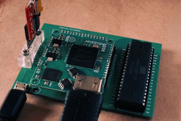
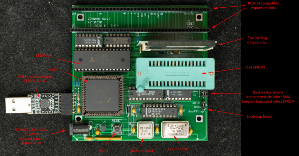
Cassette data recordings are frequency shift keyed, with the 0 and 1 of the binary information represented by different tones. An expected solution to detect these might be to use a Fourier transform, but instead he opts for a simpler solution of counting zero crossings and timing their interval. The resulting stream of data is fed into a UART from which the data itself can be reconstructed. All this is implemented on a Mercury FPGA board which contains a Xilinx Spartan 3A FPGA, but it’s a technique that could be used on other devices too.

So your FPGA retrocomputer deserves an authentic cassette interface, and now it can have one. We’d be especially impressed if all this 2020s wizardry could produce a more stable chuntey field, but we guess that might take a bit more work.

As a final aside, the project is dedicated to the memory of the pioneering Yugoslavian broadcaster [Zoran Modli], whose innovative 1980s radio show featured broadcasts of tape software for the computers of the time including our Hackaday colleague [Voja Antonić]’s Galaksija. Broadcasting software over the radio? That’s a cool hack.

Procedurally Generated Retrocomputer Emulators

[Marquis de Geek] has a profound love of old systems. Tired of writing new emulators from scratch for each project, his newest project EMF generates the emulator for him. An XML document describes the layout of the memory, CPU description, and screen handler. The output is currently a single-page Javascript emulator application with an assembly and a dissembler. However, but that backend can easily be swapped to another language such as Rust or C++.

Since EMF is a framework that provides a common way to describe the emulated machine, you get a common emulator user interface for free. There’s a lot of flexibility offered here as well. Opcodes can be implemented as a large switch statement or individual functions, depending on the target language’s performance. Self-modifying code can be detected and handled separately. Custom features or hardware can be injected easily by writing a module in the target language.

While the source code for the EMF hasn’t been released yet, several of the machines that [Marquis de Geek] has built with EMF are open-source on GitHub. So far the list includes Dragon32, Sinclair ZX80, Sinclair ZX81, Sinclair ZX Spectrum, Elliott 903, Chip8, Cosmac VIP, and the MegaProcessor. Each has a live emulator that runs in your browser.

While [Marquis de Geek] hopes to release a binary version of the EMF soon, we’re very much looking forward to the EMF source coming out once the code has been cleaned up. We love the trend towards creating easier and more accessible emulators, such as this Twitter bot that runs Atari programs.

Continue reading “Procedurally Generated Retrocomputer Emulators”

Rebuilding A Hero (the Robot, Not The Sandwich)

When [Scott Baker] found a Heathkit Hero Junior on eBay, he grabbed it. He had one as a kid, but it was long sold. The robot arrived with no electronics, so the first order of business is to give it some new modern brains including an ATMega328 and a Raspberry Pi. You can see the start of the project in the video below.

So far, you can see a nice teardown of the chassis and what’s left of the little robot’s drive system. This wasn’t the big Hero-1 that you probably remember, but it was still a pretty solid platform, especially for the time it was on the market.

Continue reading “Rebuilding A Hero (the Robot, Not The Sandwich)”

“Brain In A Vat” 6502

The 6502 was a revolutionary processor for its time. Offered at a small fraction of the cost of other processors available when it was released, it became adopted in such iconic computers at the Atari 2600, the Apple II, the NES, and the Commodore 64. For that reason it’s still extremely popular among retrocomputing enthusiasts who will often go to great lengths to restore these computers or build them from scratch. [jamesbowman] had an idea to build a 6502-based computer with the processor only, leaving the rest of the computer up to an FPGA.

He describes the system as a “brain in a vat” since a real 6502 is used as the “brain” and all other functions are passed off to the FPGA. In his build he uses an FPGA board with built-in graphics abilities, but the truly interesting part of this build is how the FPGA handles memory. If a particular value is placed on the data bus of the 6502, it loops forever through the entire memory and executes all of the instructions it finds. This saved a lot of time getting this system up and running, and he is able to demonstrate it by showing a waveform on the video output of the device.

Of course you can take an FPGA and emulate an entire computer based on a 6502, but using the actual silicon in a build like this really ensures that the user can learn and understand the hardware involved without some of the other tedium of doing things such as converting old video signals to HDMI for example. It’s a great take on retrocomputing that we expect to see more of in the future.

Altair Front Panel Tutorials

If you aren’t old enough to remember when computers had front panels, as [Patrick Jackson] found out after he built a replica Altair 8800, their operation can be a bit inscrutable. After figuring it out he made a pair of videos showing the basics, and then progressing to a program to add two numbers.

Even when the Altair was new, the days of front panels were numbered. Cheap terminals were on their way and MITS soon released a “turnkey” system that didn’t have a front panel. But anyone who had used a minicomputer from the late 1960s or early 1970s really thought you needed a front panel.

Continue reading “Altair Front Panel Tutorials”

A Look Behind The “Big Boards” At Mission Control In The Golden Age Of NASA

Certified space-nerd and all-around retro-tech guru [Fran Blanche] has just outdone herself with a comprehensive look at how NASA ran the Mission Control “Big Boards” that provided flight data for controllers for Apollo and for the next 20 years of manned spaceflight.

We’ve got to admit, [Fran] surprised us with this one. We had always assumed that the graphs and plots displayed in front of the rows of mint-green consoles and their skinny-tie wearing engineers were video projections using eidophor projectors. And to be sure, an eidophor, the tech of which [Jenny] profiled a while back, was used on one of the screens to feed video into Mission Control, either live from the Moon or from coverage of the launch and recovery operations. But even a cursory glance at the other screens in front of “The Pit” shows projections of a crispness and clarity that was far beyond what 1960s video could achieve.

Instead, plots and diagrams were projected into the rear of the massive screens using a completely electromechanical system. Glass and metal stencils were used to project the icons, maps, and grids, building up images layer by layer. Colors for each layer were obtained by the use of dichroic filters, and icons were physically moved to achieve animations. Graphs and plots were created Etch-a-Sketch style, with a servo-controlled stylus cutting through slides made opaque with a thin layer of metal. The whole thing is wonderfully complex, completely hacky, and a great example of engineering around the limits of technology.

Hats off to [Fran] for digging into this forgotten bit of Space Race tech. Seeing something like this makes the Mission Control centers of today look downright boring by comparison.

Continue reading “A Look Behind The “Big Boards” At Mission Control In The Golden Age Of NASA”

This Z80 Computer Bootstraps Itself

[Plasmode] has created several Z80-compatible board designs, at least four of them using the oddball Z280. The Z280 was a special variant of a Z80 that could bootstrap itself with no external PROM, making it ideal for anyone trying to build a system on a breadboard. According to his post, the cost to build the board is about $35.

Although the 8080 CPU got a lot of glory, it was much harder to use than the Zilog Z80. The Z80 only required a single clock and power supply, so it was much easier to build a system, even on a breadboard. On top of that, the bus wasn’t multiplexed and it could refresh DRAM memory by itself. Maybe that’s why you can still get Z80-derived chips readily. There was one thing, though, you needed an EPROM or some other way to run some initial code to bootstrap your system. Zilog knew this was a problem. In those days, you had to use a special tool to burn a PROM and, unless it was erasable and you had the special UV light to erase it, any mistakes cost you a chip.

Continue reading “This Z80 Computer Bootstraps Itself”