Air Extractor Automatically Gives AC A Boost

Portable air conditioning units are a great way to cool off a space during the hot summer months, but they require some place to blow the heat they’ve removed from your room. [VincentMakes] got a portable AC unit for his home, but he found that the place he wanted to put it was too far from the only window he could use to dump the hot air. Having too long of a duct on the hot air exhaust increases the back pressure on the fan which could cause it to prematurely fail, so [Vincent] used an extractor fan to automatically give is AC unit’s exhaust a boost on its way to the window.

Because his AC can operate at low, medium, and high speeds, he chose an extractor fan that also supported multiple speeds and took care to match the airflow of the AC and extractor fan to avoid putting too much strain on either fan. He designed a system to automatically set the speed of the boosting fan to match that of the AC using a Hall effect current sensor to measure the AC unit’s power draw and an Arduino Nano for control. A custom PCB interfaces the Nano to the Hall Sensor and control relays, and we have to applaud [Vincent] for keeping the +5V DC and 230V AC far, far away from each other. In addition to this fine electronics work, [Vincent] also built an enclosure for the fan controller that allows the fan to be mounted on top at an angle, which helps avoid having hard bends in the exhaust duct.

If this has you thinking about smart air conditioners to keep cool this summer, check out this ESP8266-powered smart AC system, or this Raspberry Pi-based system that controls both AC and blinds!

Arduino Variometer In A Mint Tin

While humans have done a pretty good job of figuring out how to fly with various mechanical contrivances, the fact remains that our natural senses aren’t really well suited to being off the ground. For example, unless you have a visual reference point, determining which way is up is quite a bit harder than you might think. Which is why pilots rely on instruments such as the variometer, that determines the current rate of climb and descent, to guide them when their eyes can’t be trusted.

It’s also a very handy thing to have when paragliding, which is why [mircemk] decided to build a hand-held version using the Arduino Nano and a BMP180 pressure sensor. Since you don’t want to be staring at a little screen in mid-air, the device conveys changes in altitude with audio tones. A rising tone means you’re moving upwards, while a lower tone indicates downward travel. In the video below, you can see that it only takes a meter or two of vertical movement before the device picks up on the change.

Looking for a simple yet rugged enclosure for the device, [mircemk] found a metal mint tin that would hold the microcontroller, sensor, buzzer, and the 9 V battery that powers it all. We know what you’re thinking, but don’t worry; holes have been popped in the sides to make sure there’s no pressure difference inside the tin. There’s plenty of room to replace the alkaline battery with a rechargeable pack and associated charge controller, but we imagine there’s a certain security in tossing in a fresh new primary cell before slipping the surly bonds of Earth.

If you’re in interested DIY instrumentation for a glider or other aircraft that actually has a proper cockpit, this sunlight readable flight computer made from a Kobo e-reader would be a great start.

Continue reading “Arduino Variometer In A Mint Tin”

Arduboy On The Big Screen

We’re big fans of the Arduboy here at Hackaday, but we’ll admit its tiny screen isn’t exactly ideal for long gaming sessions. There are some DIY builds of the open source handheld that use a larger SPI OLED display, though you’re relatively limited on what kind of changes can be made to the hardware before the games start balking. But as [Nick Bild] shows with his Arduboy home console, hacking the core system library opens up a lot of interesting possibilities.

Games written for the Arduboy make use of a common library that handles all the low-level hardware stuff, which includes a display() function to push the graphical data out to an SPI-connected OLED display. What [Nick] has done is re-write that function to instead output to a custom VGA generator running on the TinyFPGA BX. He had to delete support for the Arduboy’s RGB LEDs because he needed the extra pins, but that shouldn’t cause much of a problem in terms of software support.

This does mean that games need to be recompiled against the modified library to work on his hardware, but as the vast majority of Arduboy software is open source anyway, that’s not much of a problem. We particularly like the Super Game Boy style border  you get around the display at no extra cost.

At this point the hardware looks less like a console and more like a breadboard filled with jumpers, so we’re interested in seeing this project taken to its logical conclusion. A custom PCB, enclosure, and possibly even support for using the original NES controllers would turn this into proper system worthy of any hacker’s game room. You could even put the games on custom cartridges if you wanted, though a flash chip that holds the system’s entire library would be quite a bit more convenient.

[Emily]’s Eerie Educational Electric Eyeball Entertains

Like many of us, [Emily’s Electric Oddities] has had a lot of time for projects over the past year or so, including one that had been kicking around since late 2018. It all started at the Hackaday Superconference, when [Emily] encountered the Adafruit Hallowing board in the swag bag. Since that time, [Emily] has wanted to display the example code eyeball movement on a CRT, but didn’t really know how to go about it. Spoiler alert: it works now.

See? It’s educational.

Eventually, [Emily] learned about the TV out library for Arduino and got everything working properly — the eyeball would move around with the joystick, blink when the button is pressed, and the pupil would respond visually to changes in ambient light. The only problem was that the animation moved at a lousy four frames per second. Well, until she got Hackaday’s own [Roger Cheng] involved.

[Roger] was able to streamline the code to align with [Emily]’s dreams, and then it was on to our favorite part of this build — the cabinet design. Since the TV out library is limited to black and white output without shades of gray, Emily took design cues from the late 70s/early 80s, particularly the yellow and wood of the classic PONG cabinet. We love it!

Is Your Pet Eye the worst video game ever, as [Emily] proclaims it to be? Not a chance, and we’re pretty sure that the title still rests with Desert Bus, anyway. Even though the game only lasts until the eye gets tired and goes to sleep, it’s way more fun than Your Pet Rock. Don’t miss the infomercial/explanation/demonstration video after the break. If one video is just not enough, learn more about [Emily’s] philosophy of building weird projects from the Supercon talk she presented. It’s also worth mentioning that this one fits right into the Reinvented Retro contest.

Why are eyeballs so compelling? We can’t say for sure, but boy, this eyeball web cam sure is disconcerting.

Continue reading “[Emily]’s Eerie Educational Electric Eyeball Entertains”

Speech Recognition On An Arduino Nano?

Like most of us, [Peter] had a bit of extra time on his hands during quarantine and decided to take a look back at speech recognition technology in the 1970s. Quickly, he started thinking to himself, “Hmm…I wonder if I could do this with an Arduino Nano?” We’ve all probably had similar thoughts, but [Peter] really put his theory to the test.

The hardware itself is pretty straightforward. There is an Arduino Nano to run the speech recognition algorithm and a MAX9814 microphone amplifier to capture the voice commands. However, the beauty of [Peter’s] approach, lies in his software implementation. [Peter] has a bit of an interplay between a custom PC program he wrote and the Arduino Nano. The learning aspect of his algorithm is done on a PC, but the implementation is done in real-time on the Arduino Nano, a typical approach for really any machine learning algorithm deployed on a microcontroller. To capture sample audio commands, or utterances, [Peter] first had to optimize the Nano’s ADC so he could get sufficient sample rates for speech processing. Doing a bit of low-level programming, he achieved a sample rate of 9ksps, which is plenty fast for audio processing.

To analyze the utterances, he first divided each sample utterance into 50 ms segments. Think of dividing a single spoken word into its different syllables. Like analyzing the “se-” in “seven” separate from the “-ven.” 50 ms might be too long or too short to capture each syllable cleanly, but hopefully, that gives you a good mental picture of what [Peter’s] program is doing. He then calculated the energy of 5 different frequency bands, for every segment of every utterance. Normally that’s done using a Fourier transform, but the Nano doesn’t have enough processing power to compute the Fourier transform in real-time, so Peter tried a different approach. Instead, he implemented 5 sets of digital bandpass filters, allowing him to more easily compute the energy of the signal in each frequency band.

The energy of each frequency band for every segment is then sent to a PC where a custom-written program creates “templates” based on the sample utterances he generates. The crux of his algorithm is comparing how closely the energy of each frequency band for each utterance (and for each segment) is to the template. The PC program produces a .h file that can be compiled directly on the Nano. He uses the example of being able to recognize the numbers 0-9, but you could change those commands to “start” or “stop,” for example, if you would like to.

[Peter] admits that you can’t implement the type of speech recognition on an Arduino Nano that we’ve come to expect from those covert listening devices, but he mentions small, hands-free devices like a head-mounted multimeter could benefit from a single word or single phrase voice command. And maybe it could put your mind at ease knowing everything you say isn’t immediately getting beamed into the cloud and given to our AI overlords. Or maybe we’re all starting to get used to this. Whatever your position is on the current state of AI, hopefully, you’ve gained some inspiration for your next project.

Simple Probe Sniffs Out EMI

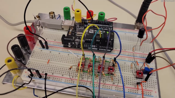
Unable to account for the strange glitches he was seeing on his DIY CNC router, [Daniël Van Den Berg]  wondered if his electronics might be suffering from some form of electromagnetic interference (EMI). So he did what any good hacker would do, and rummaged through the parts bin to build an impromptu EMI detector.

[Daniël] is quick to point out that he’s not an electrical engineer, and makes no guarantees about the accuracy of his tossed together gadget. But it does seem to work well enough in his testing that he’s able to identify particularly “noisy” electronic components, so it’s probably worth putting one together just to hear what your hardware is pumping into the environment.

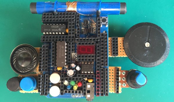
The hardware here is very simple, [Daniël] just attached a coil of solid copper wire to one of the analog pins on an Arduino Nano with a resistor, and hung a speaker off of one of the digital pins. From there, it just took a few lines of code to read the voltage in the coil and convert that into a tone for the speaker. The basic idea is that a strong alternating magnetic field will set up voltage fluctuations in the coil large enough for the Arduino’s ADC to read.

If you’re looking for a bit more insight into what kind of interference your electronic creations might be putting out, [Alex Whittimore] gave a fantastic presentation during the 2020 Hackaday Remoticon about performing RF debugging using a cheap RTL-SDR dongle.

Perfecting A 3D Printed Camera Motion Control Rig

If you’ve ever watched one of those high production value YouTube videos and wondered how they’re able to get those smooth shots where the camera seems to be spinning around an object, you were probably looking at the product of an motorized camera motion system. There’s no question these rigs can produce visually striking shots, but their high cost usually keeps them out of the hands of us lowly hackers.

Unless of course you do like [Andy], and build your own. The latest version of this impressive rig features the ability to continuously rotate thanks to commercial 12-wire slip rings, with optical endstops so the machine can still be homed at the beginning of a move. An onboard Raspberry Pi and Arduino Uno are responsible for controlling the stepper motors, the configuration of which ends up being reminiscent of a standard 3D printer.

The MQTT remote can hold a phone for live video.

The software [Andy] has come up with lets him synchronize the camera rig with a small rotating platform he built, which allows for even more complex shots as demonstrated in the video below. It also supports a very slick MQTT-enabled remote controller that he built as a previous project, which makes taking direct control over the camera and monitoring its status much easier.

Want to add a little polish to your own project videos? [Andy] has released all of the files and information you’d need to build your own version of his motion control rig, though we wouldn’t blame you for feeling a bit intimidated by this one. It might not be the most elaborate camera motion control system we’ve seen, but it’s certainly up there. If you just want an overhead video and don’t need those fancy tracking shots, perhaps a modified VESA arm would fit the bill.

Continue reading “Perfecting A 3D Printed Camera Motion Control Rig”