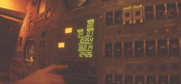
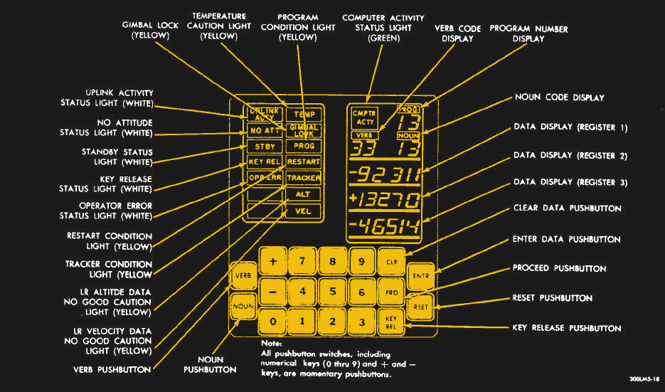
Vintage Plotter Handles Chaos With Ease

No lab in almost any discipline was complete in the 70s and 80s without an X-Y plotter. The height of data acquisition chic, these simple devices were connected to almost anything that produced an analog output worth saving. Digital data acquisition pushed these devices to the curb, but they’re easily found, cheap, and it’s worth a look under the hood to see what made these things tick.

The HP-7044A that [Kerry Wong] scored off eBay is in remarkably good shape four decades after leaving the factory. While the accessory pack that came with it shows its age with dried up pens and disintegrating foam, the plotter betrays itself only by the yellowish cast to its original beige case. Inside, the plotter looks pristine. Completely analog with the only chips being some op-amps in TO-5 cans, everything is in great shape, even the high-voltage power supply used to electrostatically hold the paper to the plotter’s bed. Anyone hoping for at least a re-capping will be disappointed; H-P built things to last back in the day.

[Kerry] puts the plotter through its paces by programming an Arduino to generate a Lorenz attractor, a set of differential equations with chaotic solutions that’s perfect for an X-Y plotter. The video below shows the mesmerizing butterfly taking shape. Given the plotter’s similarity to an oscilloscope, we wonder if some SDR-based Lissajous patterns might be a fun test as well, or how it would handle musical mushrooms.

Continue reading “Vintage Plotter Handles Chaos With Ease”

The Nintendo PlayStation: Finally Working

The Nintendo PlayStation is not a misnomer. Before the PS1, Sony teamed up with Nintendo to produce a video game console that used CD-ROMs as a distribution platform. These plans fell through, Sony went on to design the PS1, Nintendo the N64, but a few prototype ‘Nintendo PlayStations’ made it out into the wild. One of these unbelievably rare consoles was shipped to a company that eventually went into bankruptcy. The console was found when the contents of an office building were put up for auction, and last year, [Ben Heck] tore it apart.

It’s taken a year, but now this Nintendo PlayStation is finally working. This console now plays audio CDs and games written by homebrewers. The hardware lives, and a console once forgotten lives once more.

The last time [Ben Heck] took a look at the Nintendo PlayStation, the CD-ROM portion of the console was non-functional. The Super Nintendo was still functional, but for this prototype, the CD-ROM was completely self-contained and required a ‘boot cartridge’ of sorts to access anything on a CD. Somehow or another — [Ben] thinks it was a wonky cable or a dead cap — The CD-ROM came to life. Yes, jiggling a cable was the extent of the repair, after spending an inordinate amount of time reverse engineering the console.

With the CD-ROM working, [Ben] got audio playing and tried out of the few homebrew games for this PlayStation prototype. Super Boss Gaiden didn’t quite work because this game was designed to load in chunks. Another game written for this console, Magic Floor, was small enough to fit in the entirety of the CD-ROM’s buffer and loaded correctly. That doesn’t mean the game worked; there are some slight differences between the Nintendo PlayStation emulator and the actual hardware that now exists. [Ben] emailed the author of Magic Floor, and now, after a quarter-century, the Nintendo PlayStation works.

What’s next for the Nintendo PlayStation? Well, now the emulator for this system can correctly reflect the actual hardware, and hopefully the homebrewers can figure out how to write a game for this system.

Continue reading “The Nintendo PlayStation: Finally Working”

Reverse Engineering Space Invaders Sound Chip

Around here, a new blog post from [Ken Shirriff] is almost as exciting as a new Star Trek movie. This time, [Ken] tears apart a 76477 sound effects chip. This chip was state-of-the-art in 1978 and used in Space Invaders, along with plenty of other pinball machines and games.

[Ken] started out with a die photo from [Sean Riddle] and mapped its functions. Unlike a modern sound chip, this one created sounds based on networks of attached resistors and capacitors. Even if you aren’t interested in the chip, per se, [Ken] explains how the die implements active and passive devices, along with some key analog design principles like current mirrors (although we are pretty sure he got his right and his left mixed up, or maybe it was a very subtle mirror joke).

Before electronics magazines were full of computer projects, they were full of music synthesis projects and the 76477 is like a crude synthesizer on a chip. It has voltage controlled oscillators (VCOs),  and generates envelopes with specific attack and decay times to create the sounds of interest.

This reminded us a little of the sounds from the more advanced MOS6581. [Ken] has looked inside a lot of ICs, including at the 2016 Hackaday SuperConference.

Model Of A Transmission Line

Transmission lines are the kind of thing that seems to confuse beginners. After all, the fact that short-circuits can have infinite impedance and open-circuits can behave like a short is not intuitive at all!. That’s why we like [Tinselkoala]’s latest video that shows a nice model of a transmission line. It helps to understand the line as inductors and capacitors in series-parallel connection.

Any pair of wires used to transmit electrical power have tiny amounts of inductance and capacitance. This is not a problem with DC or low-frequency AC, but when the frequency is sufficiently high, weird things start to happen. The energy tends to escape as radio waves, and current reflects from discontinuities such as connectors and cable joints.  For this reason, transmission lines for high frequency signals use specialized construction to minimize those effects and reduce power losses.

[Tinselkoala] has built a model of a transmission line using coils and capacitors to simulate the inductance and capacitance of the line, with LED’s placed between the coils. He feeds the system with the signal generator with frequencies from 10 kHz to 1 MHz. In his words, they act as simple “visual voltmeters” to show the peaks and nodes of the standing waves of voltage in the line.

It is relatively simple to build your own version if you want to experiment with this fascinating subject. You will only need some magnet wire, capacitors, resistors and LED’s. If the subject sounds interesting to you,  here you can find an excellent introduction to transmission lines.

Continue reading “Model Of A Transmission Line”

How To Reverse Engineer A Chip

Have you ever wondered how you could look at a chip and map out its schematic? [Robert Baruch] wants to show you how he does it and he does in a new video (see below).  The video assumes you know how to expose the die because he’s made a video about that before.

This video focuses on using his Beaglebone-driven microscope stage to get high-resolution micrographs stitched together from smaller shots. A 3D-printed sample holder keeps the part from moving around. Luckily, there’s software to stitch the images together. Once he has the die photo, he will etch away the metal to remove the passivation, the metal layer, and the silicon dioxide under the metal and takes another set of photos.

Continue reading “How To Reverse Engineer A Chip”

Restoring A Japanese Oscilloscope

Oscilloscopes have come a long way. Today’s scope is more likely to look like a tablet than an old tube-based instrument. Still, there’s something about looking into a glowing green tube, especially if you’ve done the work to resurrect that old hollow state device. [NFM] picked up a Kikusui OP-31C–a vintage Japanese scope at a second-hand store. He made a video of his restoration efforts that you can see below.

The scope actually powered up and worked the first time. Of course, unlike a modern scope, the OP-31C has to warm up before it will show up. However, the pots needed cleaning and as a precaution, he replaced the old oil and electrolytic capacitors.

The big transformer and the coarse-looking single sided circuit board certainly will bring back memories if you are old enough. [NFM] had a schematic of the scope and takes you on a tour of the innards, although his schematic had some subtle differences from the actual unit, possibly due to some repair work.

He was going to rebuild one of the large electrolytic “can” capacitors to keep the outer shell with newer (and smaller) modern capacitors. However, he found a very similar modern capacitor and used that, instead.

We think it would have been more fun if the scope didn’t work. However, it was still a great tear down of the old tube-based device. This is a bigger device than the last old scope tear down we looked at. Not that we haven’t seen smaller ones (although, the link in the post has moved).

Continue reading “Restoring A Japanese Oscilloscope”

The Raspberry Pi Becomes A SCSI Device

SCSI devices were found in hundreds of different models of computers from the 80s, from SUN boxes to cute little Macs. These hard drives and CDROMs are slowly dying, and with that goes an entire generation of technology down the drain. Currently, the best method of preserving these computers with SCSI drives is the SCSI2SD device designed by [Michael McMaster]. While this device does exactly what it says it’ll do — turn an SD card into a drive on a SCSI chain — it’s fairly expensive at $70.

[GIMONS] has a better, cheaper solution. It’s a SCSI device emulator for the Raspberry Pi (original link dead, here’s the new location of this writeup). It turns a Raspberry Pi into a SCSI hard drive, magneto-optical drive, CDROM, or an Ethernet adapter using only some glue logic and a bit of code.

As far as the hardware goes, this is a pretty simple build. The 40-pin GPIO connector on the Pi is attached to the 50-pin SCSI connector through a few 74LS641 transceivers with a few resistor packs for pullups and pulldowns. The software allows for virtual disk devices – either a hard drive, magneto-optical drive, or a CDROM – to be presented from the Raspberry Pi. There’s also the option of putting Ethernet on the SCSI chain, a helpful addition since Ethernet to SCSI conversion devices are usually rare and expensive.

Officially, [GIMONS] built this SCSI hard drive emulator for the x68000 computer, developed by Sharp in the late 80s. While these are popular machines for retrocomputing aficionados in Japan, they’re exceptionally rare elsewhere — although [Dave Jones] got his mitts on one for a teardown. SCSI was extraordinarily popular for computers from the 70s through the 90s, though, and since SCSI was a standard this build should work with all of them.

If your retrocomputer doesn’t need a SCSI drive, and you’re feeling left out of the drive-emulation club, the good news is there’s a Raspberry Pi solution for that, too: this Hackaday Prize entry turns a Pi into an IDE hard drive.

Thanks [Gokhan] for the tip!