We all remember the video games of our youth fondly, and many of us want to relive those memories and play those games again. When we get this urge, we usually turn first to emulators and ROMs. But, old console and computer games relied heavily on the system’s hardware to control the actual gameplay. Most retro consoles, like the SNES for example, rely on the hardware clock speed to control gameplay speed. This is why you’ll often experience games played on emulators as if someone is holding down the fast forward button.
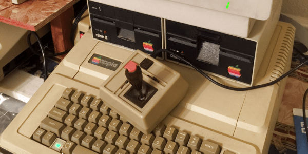
The solution, of course, is to play the games on their original systems when you want a 100% accurate experience. This is what led [FozzTexx] back to gameplay on an Apple II. However, he quickly discovered that approach had challenges of its own – specifically when it came to the joystick.
The Apple II joystick used a somewhat odd analog potentiometer design – the idea being that when you pushed the joystick far enough, it’d register as a move (probably with an eye towards smooth position-sensitive gameplay in the future). This joystick was tricky, the potentiometers needed to be adjusted, and sometimes your gameplay would be ruined when you randomly turned and ran into a pit in Lode Runner.
The solution [FozzTexx] came up with was to connect a modern USB gamepad to a Raspberry Pi, and then set it to output the necessary signals to the Apple II. This allowed him to tune the output until the Apple II was responding to gameplay inputs consistently. With erratic nature of the original joystick eliminated, he could play games all day without risk of sudden unrequested jumps into pits.
The Apple II joystick is a weird beast, and unlike anything else of the era. This means there’s no Apple II equivalent of plugging a Sega controller into an Atari, or vice versa. If you want to play games on an Apple II the right way, you either need to find an (expensive) original Apple joystick, or build your own from scratch. [FozzTexx] is still working on finalizing his design, but you can follow the gits for the most recent version.