A Really, Really Tiny Tube Amp

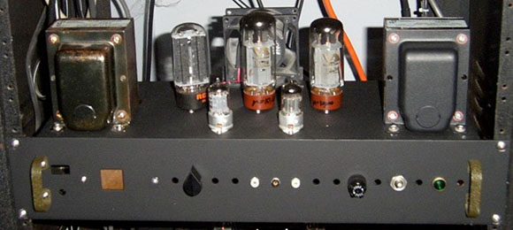
After building his first tube amp from a kit, he set to work on his next amp build. Since tube amps are a much more experimental endeavor than their solid state brethren, [Jarek] decided to make his next amp unique with military surplus subminiature tubes, and in the process created the smallest tube amp we’ve ever seen.

Instead of bulky 12AX7s and EL34s tubes usually found in tube amp build, [Jarek] stumbled upon the subminiature dual triode 6021 tube, originally designed for ballistic missiles, military avionics, and most likely some equipment still classified to this day. These tubes not only reduced the size of the circuit; compared to larger amps, this tiny amplifier sips power.

The 100+ Volts required to get the tubes working is provided by a switched mode power supply, again keeping the size of the final project down. The results are awesome, as heard in the video after the break. There’s still a little hum coming from the amp, but this really is a fabulous piece of work made even more awesome through the use of very tiny tubes.

Continue reading “A Really, Really Tiny Tube Amp”

In-depth Look At An LVCD Board From A Saturn V Rocket

saturn-v-lvdc-board

Join [Fran] as she dons the hat of an electronics archaeologist when looking at this vintage circuit board from the space race. As part of her personal collection she somehow acquired a Launch Vehicle Digital Computer board for a Saturn V rocket. This particular unit was never used. But it would have been had the Apollo program continued.

[Fran] is enamored with this particular board because she believes it is the forerunner of modern digital circuit design and layout. Since routing circuit boards is part of what she does for a living you can see why this is important to her. Also, who isn’t excited by actual hardware from the space program? We’ve embedded two of her videos after the break. In the first she shows off the component to the camera and speaks briefly about it. But the second video has her heading to the dentist’s office for X-rays. The image above is a rotating X-ray machine, but it looks like the best imagery comes when a handheld gun is used. They get some great images of the traces, as well as the TTL components on the board itself.

Continue reading “In-depth Look At An LVCD Board From A Saturn V Rocket”

Building A New Motherboard For A TRS-80

Trash80

The TRS-80 Model 100 was an amazing piece of kit when it was released. Able to run for a week with just four AA batteries and smaller than some laptops today, this portable version of the TRS-80 saw action with war correspondents covering the Falklands invasion. A pedigree a MacBook Pro will never be able to live up to, it seems.

[Hudson] picked up a non-functioning Model 100 with the express goal of replacing the 30-year-old electronics inside with an updated motherboard – and also pull up our retro site in the process. Armed with a Teensy++, [Hudson] pried open his ancient computer and set to work interfacing the display and keyboard to his AVR dev board.

The LCD display in the Model 100 has a resolution of 240×64, driven by ten Hitachi HD44102 display drivers. Each of these display drivers are responsible for the pixels in a 50×32 rectangle on the screen and are interfaced with a 30-bit wide bus consisting of chip select lines, and 8-bit data bus, and a few other random control lines. [Hudson] plugged this 30 pin header into his Teensy++ and after a bit of ingenuity regarding the strange electrical requirements of the LCD, was able to control every pixel on this 30-year-old display.

The next order of business was interfacing the keyboard with a modern microcontroller. The keyboard is laid out in a normal matrix, but with a few oddities: characters like ~, |, and curly brackets aren’t present on the Model 100. After working these problems out, [Hudson] set to work on a VT100 terminal emulator. This allowed him to run vi and lynx, enabling him to pull up the Hackaday retro site in a wonderful forty-column text mode.

Future improvements to this redesign include designing a proper PCB to replace the current protoboard design. The original Model 100 included a text editor and programming language, and adding a Forth implementation isn’t out of [Hudson]’s grasp. It’s an awesome build, and an excellent improvement that will allow [Hudson]’s Trash-80 to see another 30 years of use.

Frankenstein, An All-tube Home Theater Amplifier

amp

Here’s an exercise in excess if we’ve ever seen one. While working on his undergrad at Michigan State, [Gregory] thought it would be a great idea to build an all-tube home theater system. He calls his seven-foot tall rack of amplifiers ‘Frankenstein,’ and we’ve got to agree this build is an impressive monstrosity of engineering prowess.

[Gregory]’s Frankenstein is a complete 5.1 home theater system. In the interests of sanity, the majority of the equipment in the rack is off-the-shelf gear including a CD player, surround sound processor, and a beautiful McIntosh solid state preamp. The power amps, though, are where this build really shines.

For the sub, [Gregory] built a wonderful monoblock tube amp, able to push nearly 300 watts into a subwoofer. The other channels for this home theater system are amplified with a huge four channel tube amp providing 480 watts per channel. In total, there are 23 tubes in [Gregory]’s amplifier system, enough to consume 20 amps of filament current.

You can check out [Gregory]’s demo video of his system after the break.

Continue reading “Frankenstein, An All-tube Home Theater Amplifier”

Fabricating Hardware From The Original Arcade Pong Schematics

original-arcade-pong-rebuild

This heavily populated PCB is a recreation of the original arcade version of Pong. That is an important distinction because the home version of Pong used a specialized chip to do much of the work. This is basically all stock logic, which explains the high component count. We wonder how many quarters it took just to pay for all 66 chips at the time?

[Pong74ls] was the person who took on this project. There is an original schematic available, but it’s incredibly crowded and rather difficult to figure out. Fortunately [Dan Boris] has already done a lot of the heavy work. He took the one-page nightmare and turned it into a sixteen page plan for building the original board (look for the schematic link under technical details).

Before the board could be laid out some redesign work was necessary. It sounds like some of the original chips are out of production and suitable replacements needed to be found. The board was then laid out in Eagle before sending the design off to a fab house. There was just one error which didn’t allow the ball to bounce when hitting a paddle while travelling downward. A couple of jumper wires fixed that right up!

[via Reddit]

[Original Reddit Post]

[Staci Elaan]’s Awesome Portable Tesla Coils.

We stumbled onto [Staci’s] videos a while ago when we posted this big tesla gun. While it wasn’t the first portable coil we had seen, it was certainly an impressive implementation. In the comments we found [Staci] had already been making these for a while. Hers were big and small, had awesome modulation, and looked freaking cool too.

It also should be pointed out that [Staci] donates her coils to people when she’s done! Let me say that again, she gives them away to groups of people that could use them. That deserves some respect.

Unfortunately, [Staci] didn’t document her builds in great detail at the time. She has added some information recently though.   You can read about her first working prototype from 2006, or a slightly more modern one here.

Of course, the real fun is in seeing them work.

Continue reading “[Staci Elaan]’s Awesome Portable Tesla Coils.”

An Introduction To Vector Displays

clock

Unlike the CRTs found in big old televisions, vector displays are a bit of a historical oddity. Instead of sweeping an electron beam across the screen from left to right and top to bottom, a vector display draws lines between two points on a screen. Once used in arcade games such as AsteroidsTempest, and old FAA displays, vector monitors have fallen out of favor due to either the complexity or difficulty in acquiring the needed CRT. The folks over at NYC Resistor put up a great tutorial for getting a vector display up and running, and even managed to put a clock on an oscilloscope.

The key component of getting a vector display to work is the digital to analog converter. This DAC takes voltages from eight pins on a Teensy 2.0 dev board and converts them to a voltage anywhere in between 0 and 5 Volts. After connecting the output of this DAC to an input on an oscilloscope, the microcontroller can draw a line between any two points on an axis.

In the video after the break, you can see two of these DACs connected to an oscilloscope displaying a clock. It’s a very cool piece of work, and something that finally gives a purpose to the ancient CRT oscilloscope you might have lying around.

Continue reading “An Introduction To Vector Displays”