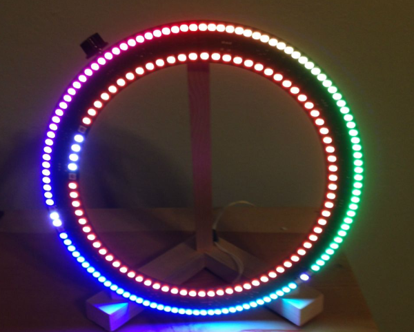
We don’t think we’ve seen an Infinity Mirror Clock before, but we love this new twist on an old favorite. Different colors distinguish between seconds, minutes and hours, and an additional IR sensor detects when someone is directly in front of the clock and switches the LEDs off, allowing it to be used as a normal mirror. This build is the work of [Dushyant Ahuja], who is no stranger to hacking together clocks out of LEDs. You can tell how much progress he’s made with the mirror clock by taking a glance at his first project, which is an impressive creation held together by jumbles of wire and some glue.
[Dushyant] has stepped up his game for his new clock, attaching an LED strip along the inside of a circular frame to fashion the infinity mirror effect. The lights receive a signal from an attached homemade Arduino board, which is also connected to a real-time clock (RTC) module to keep time and to a Bluetooth module, which allows [Dushyant] to program the clock wirelessly rather than having to drag out some cords if the clock ever needs an adjustment.
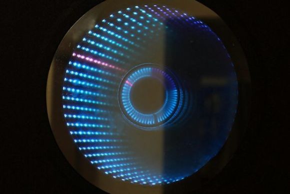
Stick around after the jump for a quick demonstration video. The lights are dazzling to watch; [Dushyant] inserted a stainless steel plate at the center of the circle to reflect the outer rim of LEDs. After a quick rainbow effect, it looks like the mirror enters clock mode. See if you can figure out what time it is. For a more step-by-step overview of this project, swing by his Instructables page.
Continue reading “Infinity Mirror Clock: There’s A Time Joke There Somewhere”