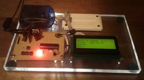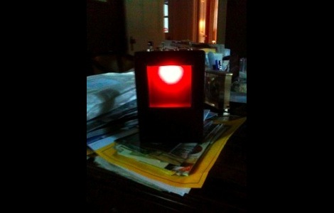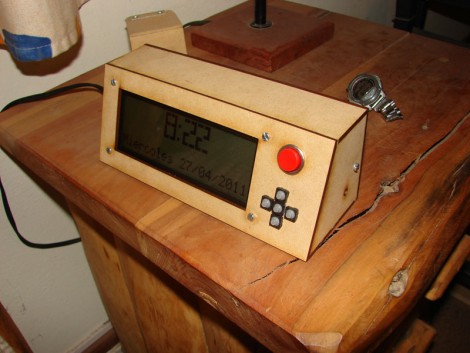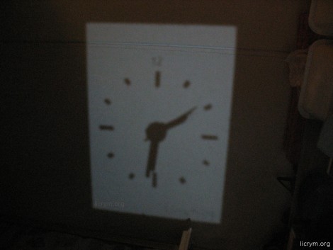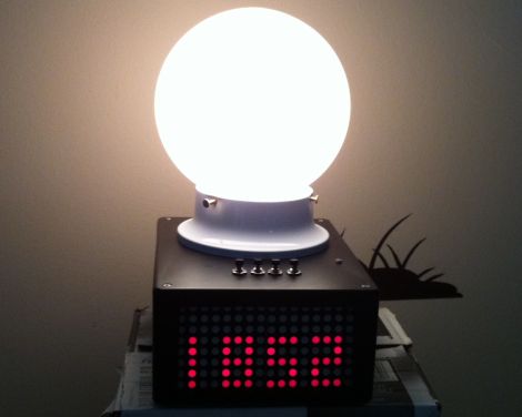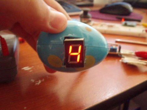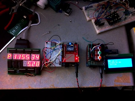
Here’s a three digit binary clock that [Viktor] designed. It uses a multiplexed display to drive one digit at a time with a PIC 16F628A. The video after the break shows it ticking away, display hours, minutes, and seconds in blue LEDs. You may be wondering why those LEDs are not flush to the board? [Viktor] took the project one step further than most binary clock projects, designing a PCB to fit into the enclosure of an old laptop PSU and then having the board manufactured. With options like DorkbotPDX groups orders its has become quite inexpensive to do this and it’s really good practice for when you need to design a highly complicated board for that super-fantastic project of the future.
clock hacks977 Articles
DOTKLOK
[Andrew] is showing off his latest creation, an LED matrix clock, which he is calling “DOTKLOK”. The clock is powered by an atmega328 micro controller with a real time clock module keeping the time. The display is made out of a grid of 8×8 LED matrices giving it a resolution of 24×16, and is all housed in an attractive acrylic housing.
The clock animations are inspired by classic video games such as Pong, Tetris, Pacman, and Space Invaders. Since the software is open, it is easy to jump into the Arduino source and add or modify animations to suit your taste, or even use the clock as a custom display for non clock related applications.
Available as a kit or fully assembled if youre needing a gift for that special nerdy someone. If you would like to go it alone, source, schematics, pcb, and enclosure files are available along with a bill of materials.
Join us after the break to see a short video of this fun clock in action
Pong Clocks Using LED Matrix Modules
We love Pong clocks because they’re showpieces. This particular offering, called the Wise Clock, is the third hardware revision of the project. The LED display is dead simple since they’re using a 32×16 bi-color module from Sure Electronics. If you don’t want to design and build your own multiplexing display this is a somewhat inexpensive and high-performance alternative.
After the break you can see that the paddle movements look very realistic. They move like a human player might, which is quite often not the case with these clocks. If you want to see how that’s done, check out the code which was originally developed by [123led] for a different project.
How To Build A Ping-pong Ball Display
If you’ve been lusting after your own glowing display we’re here to help by sharing some simple building techniques that will result in an interesting project like the one you see above. This is a super-accurate clock That uses ping-pong balls as diffusers for LEDs, but with a little know-how you can turn this into a full marquee display. Join me after break where I’ll share the details of the project and give you everything you need to know to build your own.
Continue reading “How To Build A Ping-pong Ball Display”
Xbee Controlled, Granite-wrapped Clock Travels Into Future
From the looks of it this clock is a couple of months ahead of its time. [Oscar] built the clock (translated) taking time to add a lot of goodies into the mix. First up, the parts you see include six large 7-segment displays for hours, minutes, and seconds as well as an LED marquee which can scroll messages. Inside there’s a temperature and humidity sensor for environmental feedback, and an Xbee module which allows for wireless computer control. Time is kept by a DS1307 real-time clock, which is read by an Arduino Uno, then pushed to the display by the pair of I2C addressable SAA1064 drivers. The whole thing was enclosed in four sheets of granite for the box, and a pane of glass for the front. We sure hope it’s well anchored to that wall. You can see it ticking away after the break.
Continue reading “Xbee Controlled, Granite-wrapped Clock Travels Into Future”
Edison Clock Uses Ammeter Plus Bulbs To Set Alarm
This is the Edison clock, designed by [David Krawczyk]. It shows time in the same way as the multimeter clock, regulating power to two analog needle meters. The feature that makes this one a bit different is the alarm. You can see the series of holes on the front of the base. These have a small light bulb socked in each, and correspond to hours and 5-minute increments. Insert two bulbs to set the alarm time, and make sure that the alarm knob points to ‘on’. As you can see above, the alarm has been set to 8:15. Hidden on the last image of the article above is a PDF with just a bit more explanation. Still, much has been left out so if you replicate this clock we want to hear about it.
Binary Clock Using Logic Chips And Mains Frequency
[Osgeld] built himself a binary clock. He didn’t take the time to explain his project, but he did post beautifully hand-drawn schematics and pictures of the circuit (PDF) as he was building it. We’ve seen clock projects that use mains frequency as the clock source and that’s the route that [Osgeld] chose for his build. He started with a 9-12V AC wall wort as a power input. From there it’s just a matter of using a bridge rectifier to convert to DC, then a 7805 linear regulator to establish a steady 5V rail. A resistor and a couple of diodes allow him to pull the 60 Hz frequency off of the incoming AC, and then use a combination of 4000 and 7400 logic chips to count the pulses and keep track of the time.