Tiny Bubbles In The Clock

When [DonHo] sang about tiny bubbles, he probably wasn’t thinking of them embedded in glycerine. But that’s where the bubbles in [ShinodaY]’s clock reside. The viscous fluid holds the bubbles better allowing the time to be read more easily. You can watch the relaxing display in the video below.

The theory of operation is simple and reminds us somehow of a reverse Tetris game. Solenoid valves at the base release air bubbles to form a row of the display. The bubbles rising makes room for the next row. The display has as many columns as there are air outlets at the bottom. Spacing the bubble pixels is as simple as adjusting the timing between air bubbles.

Continue reading “Tiny Bubbles In The Clock”

Numitron Clock Is A Tidy ’70s Throwback

As far as hacker clock builds go, the more obscure the parts involved, the better. By this yardstick, [sjm4306] has a great piece on his hands with this Numitron-based build.

The Numitron was a type of display popular in the 1970s, and often used in aircraft avionics and other high-end hardware. The display is a 7-segment type, but using filaments instead of LEDs. [sjm4306] was able to lay his hands on four of these devices, along with some bulbs to act as the digit seperator and AM/PM indicator. Due to being incandescent in nature, multiplexing wasn’t a practical option, with lower duty cycles drastically dimming the display. Instead, a 32-bit cascaded shift register was used to enable all the segments to be driven at the same time.

It’s a great build that uses some genuine original display hardware to create a clock with a compelling vintage aesthetic. This would make a great gift to a pilot from the era, or any hacker that likes the unusual display technologies of yesteryear. You can even build a Numitron watch, if you’re so inclined. Video after the break.

Continue reading “Numitron Clock Is A Tidy ’70s Throwback”

It’s About Time We Saw Another Infinity Mirror Clock

Have you made an infinity mirror yet? They’re pretty much a rite of passage project at this point. But unlike that DIY power supply, most of them serve no function beyond looking cool (not that there’s anything wrong with that). Might as well make it do something, right?

[How Do You – DIY] has a built a few mirrors because he likes experimenting with the effects of different reflective surfaces in various positions. This time, he’s built a clock from the ground up. Basic infinity mirror rules apply here, though he used semi-transparent reflective film on both sides for greater effect and put an adjustable warping bar in the back so the trail curves toward the center. The actual timekeeping is done by an Arduino Nano.

The RGB LEDs on his strip were a few millimeters too far apart for his liking, so he added a few dozen hours to the build by cutting it apart and painstakingly placing them all around the wood frame. Then he Dremeled a groove for each set of three wires that link the LEDs so that they sit flush. The final product is beautiful, and it’s a shame that this LED-holding frame is hidden away inside the equally well-crafted aluminium frame.

Don’t waste another minute — sweep past the break to check out the build video. If it’s a portable and functional conversation piece you want, make a set of infinity mirror coasters.

Oh, and did we mention that we’re running a clock contest? Hint, hint.

Continue reading “It’s About Time We Saw Another Infinity Mirror Clock”

Custom Nixies Perform When Cranked Up To 100,000 Hertz

With the popularity of Nixie clocks, we’d be forgiven for thinking that the glowing tubes are only good for applications with a stately pace of change. But we forget that before they became the must-have hobbyist accessory, Nixies were used in all kinds of scientific instruments, from frequency counters to precision multimeters. In such applications, update rates in the hundreds or thousands of Hertz aren’t uncommon, and the humble Nixie handled display refreshes with ease.

But what about refreshing a Nixie at 100 kHz? That was the question put to artisanal Nixie maker [Dalibor Farný] by a client who wanted a timer to calibrate high-speed cameras. It was a feat that [Dalibor] wasn’t sure his custom-made tubes could handle. The video below shows his efforts to find out.

If you ever wanted to know about the physics of gas-discharge displays like the Nixie, the fifteen minutes starting at about 5:13 will give you everything you need. That basic problem boils down to the half-life of excited neon, or how long it takes for half the population of excited molecules to return to the ground state. That, in turn, dictates how long a given cathode will continue to visibly glow after it’s turned off, which determines how many digits will appear illuminated at once.

To answer that, they engaged a company in Prague with a camera capable of a mind-blowing 900,000 frames per second. Even though they found a significant afterglow period for each cathode, even at 100 kHz it’s clear which digit is the one that’s currently illuminated. They also looked at the startup of digits in a cold Nixie versus one that’s warmed up, leading to some fascinating footage at around 26:30.

We appreciate [Dalibor]’s attention to detail, not only in the craftsmanship of his custom tubes but in making sure they’re going to do their job. He recently did a failure analysis on some of his high-end clocks that showed the same care for his product and his brand.

Continue reading “Custom Nixies Perform When Cranked Up To 100,000 Hertz”

Tracking Wasted Time With A Ferrofluid Clock

We know this project is supposed to be about developing a fine-looking ferrofluid clock, and not about the value of procrastination. But after watching the video below, see if you don’t think that procrastination has taken these two students further than expected.

We first ran into [Simen] and [Amund] several months ago when they launched their ferrofluid project in a fit of “There’s got to be more to life than studying.” It seemed then that building a good-looking, functional ferrofluid display would be a temporary distraction, but the problems posed proved to be far deeper and thornier than either of the electrical engineering students expected. The idea is simple: contain a magnetic fluid between two transparent panels and create pixels using an array of electromagnets to move dots of the fluid around. The implementation, however, was another matter, with the ferrofluid itself proved to be the biggest obstacle. All the formulas they tried seemed to coagulate or degrade over time and tended to stain the glass. While the degradation was never fully sorted, they managed to work around the staining by careful cleaning of the glass and using a saturated brine solution to fill the container.

Backed by 252 electromagnets and drivers on ten custom PCBs, the video below shows the (mostly) finished panel in action as a clock. We’re impressed by the smoothness of the movements of each pixel, even if there’s a bit of drooping at the bottom thanks to gravity. As for the future of the project, that’s unclear since [Simen] is headed off for a NASA internship. We’re not sure if that was despite or because of this procrastination-driven project, but we congratulate him either way and look forward to hearing more from both of them in the future.

Continue reading “Tracking Wasted Time With A Ferrofluid Clock”

New Contest: Tell Time

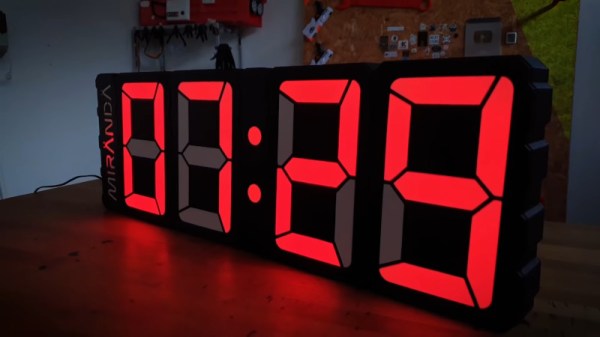
Clocks. You love ’em, we certainly love ’em. So you hardly need a reason to take on a new clock build, but it makes it much sweeter when you know there’s a horde of people waiting to fawn over your creation. Hackaday’s Tell Time Contest is a celebration of interesting timepieces. Show off a clever way to mark the passage of time and gain the adoration of your peers, and maybe even score a prize!

The Rotating Moon Clock is an interesting take on a timepiece

From now until January 24th, you can enter your Hackaday.io project by using the “Submit project to…” menu on the left sidebar of your project page. There is only one main constraint: it needs to somehow represent time. Microseconds or millennia, minutes until the next bus arrival or centuries until Pluto completes its next orbit, we don’t care as long as you find it interesting.

Document your timepiece with pictures, a description, and all of the technical details. Three outstanding entries will each receive a $100 cash prize, based on craftsmanship, function, and creativity.

Tick-tock… don’t delay. Time’s slipping away to have your quirky clock immortalized on Hackaday.

Antique Pocket Watch Project Updates Antique Pocket Watch

Here at Hackaday we have a bit of a preoccupation with timepieces. Maybe it’s the deeply personal connection to an object you wear on your body, or the need for ultimate reliability. Perhaps it’s just a fascination with the notion of time itself. Whatever the case, we don’t seem to be alone as there is a constant stream of time-related projects coming through our virtual doors. For this article we’ve unearthed the LED Pocketwatch 1.0 by [Dr. Pauline Pounds] from way back in 2009 (ironically via a post about a wristwatch from last year!). Fortunately for us the Internet Archive has saved this heirloom nouveau from the internet dustbin so we can appreciate the craftsmanship involved in [Dr. Pounds]’ work.

Check out the wonderful, spiral routing!

My how far we’ve come; a decade after this project was posted a hacker might choose to 3d print a case for a new wearable, but in 2009 that would have been an entire project by itself! [Dr. Pounds] chose to use the casing from an antique Elgin pocket watch. Even through the mists of a grainy demo video we can imagine how soft the well-worn casing must be from heavy use. This particular unit was chosen because it was a hefty 50mm in diameter, leaving plenty of room inside for a 44mm double sided PCBA with 133 0603 LEDs (60 seconds, 60 minutes, 12 hours), a PIC 16F946, an ERM, and a 110mAh LiPo. But what really sets the LED Pocketwatch 1.0 apart is the user interface.

The ERM is attached directly to the rear of the case in order to best conduct vibration to the outside world. For maximum authenticity it blips on the second, to give a sense that the digital watch is mechanically ticking like the original. The original pocket watch was designed with a closing lid which is released when the stem is pressed. [Dr. Pounds] integrated a button and encoder with the end of the stem (on the PCBA) so the device can be aware of this interaction; on lid open it wakes the device to display the time on the LEDs. The real pièce de résistance is that he also integrated a minuscule rotary encoder, so when the stem is pressed you can rotate it to set the time. It’s all quite elegantly integrated and imminently usable.

At this point we’d love to link to sources, detailed drawings, or CAD files, but unfortunately we haven’t found any. If this has you inspired check out some of the other pocket watches we’ve posted about in the past. If you’re interested in a live demo of the LED Pocketwatch 1.0, check out the original video after the break.

Continue reading “Antique Pocket Watch Project Updates Antique Pocket Watch”