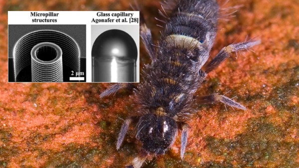
“We want to put water right into your processor.” If that statement makes you sweat, that is good. Sweating is what we’re talking about, but it’s more involved than adding some water like a potted plant. Sweating works naturally by allowing liquid to evaporate, and that phase change is endothermic which is why it feels cool. Evaporative coolers that work in this way, also known as swamp coolers, haven’t been put into computers before because they are full of sloshy water. Researchers in South Korea and the United States of America have been working on an evaporative cooling system mimicking the way some insects keep themselves cool by breathing through their exoskeletons while living in damp soil.
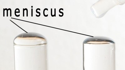
Springtails are little bugs that have to keep the water and air separate, so they don’t drown in the wet dirt where they live. Mother Nature’s solution was for them to evolve to do this with columns that have sharp edges at the exit. Imagine you slowly add water to a test tube, it won’t spill as soon as you reach the top, it will form a dome. This is the meniscus. At a large scale, say a river dam, as soon as you get over the dam you would expect spillage, but at the test tube level you can see a curve. At the scale of the springtail, exuded water will form a globe and resist water pressure. That resistance to water pressure allows this type of water cooling to self-regulate. Those globes provide a lot of surface area, and as they evaporate, they allow more water to replenish the globe. Of course, excessive pressure will turn them into the smallest squirt guns.
We have invented a lot by copying Mother Nature. Velcro was inspired by burrs, and some of our most clever robots copy insects. We can also be jerks about it.
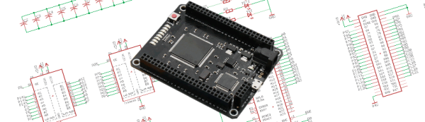
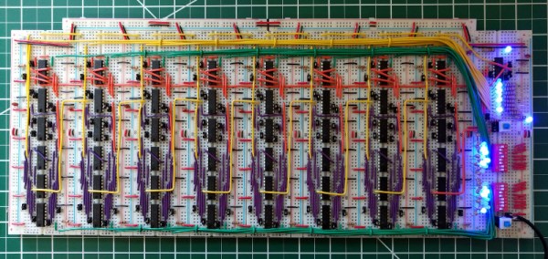
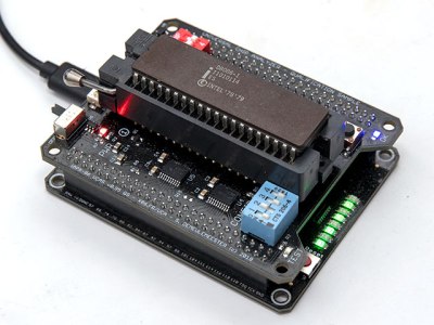 So, how does it actually test? Synthesized inside the FPGA is everything the CPU needs from the motherboard to make it tick, including ROM, RAM, bus controllers, clock generation and interrupt handling. Many testing frequencies are supported (which is helpful for spotting fakes), and if connected to a computer via USB, the UCA can check power consumption, and even benchmark the chip. We can’t begin to detail the amount of thought that’s gone into the design here, from auto-detecting data bus width to the sheer amount of models supported, but you can read more technical details