While this is not exactly a hack or a fail, it definitely is an inspiring example on how to debug a faulty card.
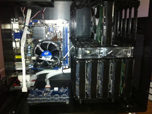
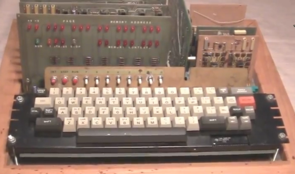
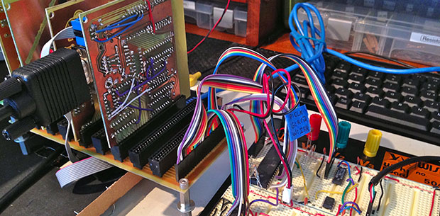
[Quinn] is one of the very few hobbyists out there that designed her own 6502 based computer. For the young readers of Hackaday, the MOS 6502 was introduced in 1975 and has been used in the Aple // line, the Commodore 64, the Vic-20, the Atari computers, the Nintendo Enterntainment System and others.
[Quinn]’s homemade new RAM board had been working for many weeks until it started to show some weaknesses by only sporadically passing the boot RAM test. Assuming the RAM was the problem, she started by making a more advanced memory test, which showed errors at random addresses.
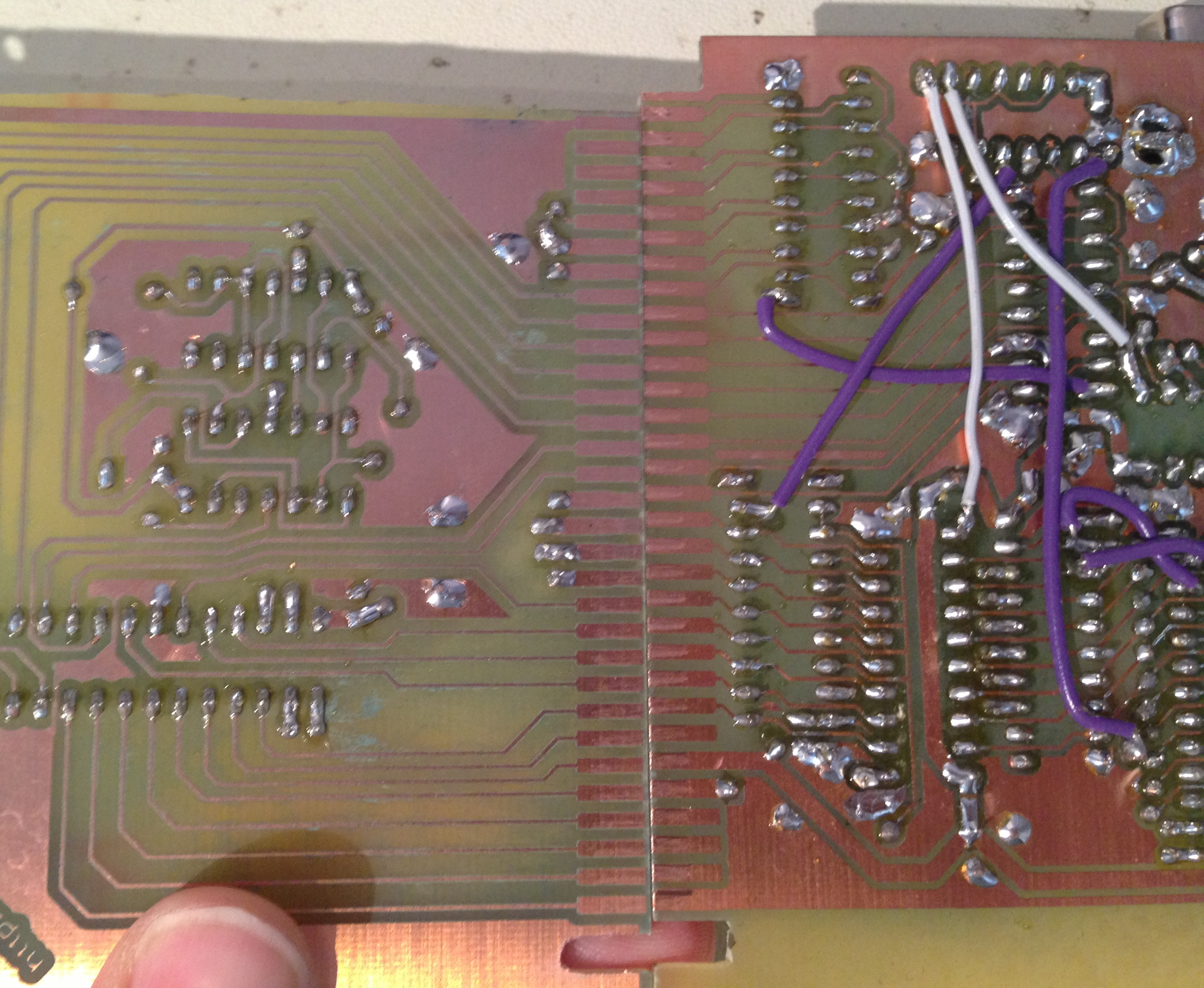
She didn’t have any more of the same memory chips on hand which could be used with a fresh PCB. Determined to power through the issue, she etched a new board with a new memory design. Unfortunately it also gave memory errors at boot. Only one culprit was left, which is shown in the picture above. It’s a small sizing error in the board artwork which was just enough to cause a misalignment on the connector.
The article contains many details about her debugging process, so it definitely is worth the read.