So you fancy yourself a FOSS devotee, do you? Running GNU/Linux on your old ThinkPad, avoiding devices that need binary blobs? Got LibreBoot installed too? Not bad, not bad. But what about the hard drive? Can you be sure you aren’t leaking some freedoms out of that spinning rust?
Well, worry no more. Thanks to the work of [dosdude1], we now have an open source solid state drive that’s designed to work with any device which originally used a 2.5 inch IDE hard drive. The choice of releasing it under the GPL v3 versus an open hardware license might seem an odd choice at first, but turns out that’s actually what the GNU project recommends currently for circuit designs.

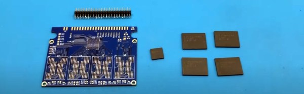
Which is precisely what we’re talking about here — just a circuit design done up in KiCad. There’s no firmware required, and the PCB features very little beyond the four BGA152/BGA132 NAND flash chips and the SM2236 controller IC. You’ve just got to get the board fabricated, obtain (or salvage) the chips, and suddenly your retro laptop is sporting the latest in mass storage technology.
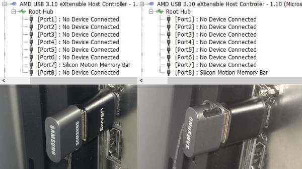
So how does it work? The SM2236 is actually a CompactFlash (CF) controller, and since IDE and CF interfaces are so similar, the PCB doesn’t have to do much to adapt from one to the other. Sprinkle in a few NANDs, and you’ve got yourself a native SSD suitable for old school machines. [dosdude1] says the board can slot four 64 GB chips, which should be more than enough given the age of the systems this gadget will likely be installed in. There are a few catches though: the NAND chips need to be supported by the SM2236, and they all have to match.
If you need something even smaller, [dosdude1] produced a 1.8 inch SSD using the same techniques back in October of last year.
Continue reading “That Old ThinkPad Needs An Open Source 2.5″ IDE SSD”

 [HolGer71] starts with