Marketing and advertising groups often have a tendency to capitalize on technological trends faster than engineers and users can settle into the technology itself. Perhaps it’s no surprise that it is difficult to hold back the motivation to get a product to market and profit. Right now the most glaring example is the practice of carelessly putting WiFi in appliances and toys and putting them on the Internet of Things, but there is a similar type of fiasco playing out in the electric power industry as well. Known as the “smart grid”, an effort is underway to modernize the electric power grid in much the same way that the Internet of Things seeks to modernize household appliances, but to much greater and immediate benefit.
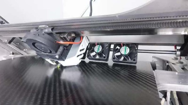
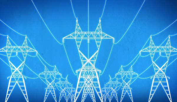
Photo by Bryan Cockfield
To that end, if there’s anything in need of modernization it’s the electric grid. Often still extensively using technology that was pioneered in the 1800s like synchronous generators and transformers (not to mention metering and billing techniques that were perfected before the invention of the transistor), there is a lot of opportunity to add oversight and connectivity to almost every part of the grid from the power plant to the customer. Additionally, most modern grids are aging rapidly at the same time that we are asking them to carry more and more electricity. Modernization can also help the aging infrastructure become more efficient at delivering energy.
While the term “smart grid” is as nebulous and as ill-defined as “Internet of Things” (even the US Government’s definition is muddied and vague), the smart grid actually has a unifying purpose behind it and, so far, has been an extremely useful way to bring needed improvements to the power grid despite the lack of a cohesive definition. While there’s no single thing that suddenly transforms a grid into a smart grid, there are a lot of things going on at once that each improve the grid’s performance and status reporting ability.