VHDL and Verilog are hardware description languages, used to describe and define logic circuits. They’re typically used to design ASICs and to program FPGAs, essentially using software to define hardware. However, [Tim] has done something altogether quite creative, creating tools to take VHDL and Verilog and spit out PCB designs for discrete logic.
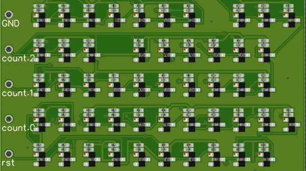
Yes, you read that correctly. The basic idea is to take VHDL source code, and then make a PCB layout that implements the desired logic using resistor-transistor logic. From there, the PCB design files can be shipped off to a manufacturer for pick-and-place assembly at a fraction of the cost of producing a bespoke ASIC.
The drawbacks are obvious; tons of individual discrete parts are required, the size penalty is hilariously bad, and power usage is almost certainly orders of magnitude higher than doing the same logic on an ASIC or even FPGA. Oh, and everything’s much slower, too.
However, as an academic exercise or simply for fun, it’s an awesome bit of work. The idea that one can define a complicated logic circuit and have a PCB implementing the logic whipped up by automated tools is amazing, and we absolutely want to see more of this type of thing.
We’ve seen similar work done with VHDL synthesis into 74-series logic design. If you’ve been developing your own fancy digital-logic-fu, be sure to drop us a line!
[Thanks to Yann Guidon for the tip!]