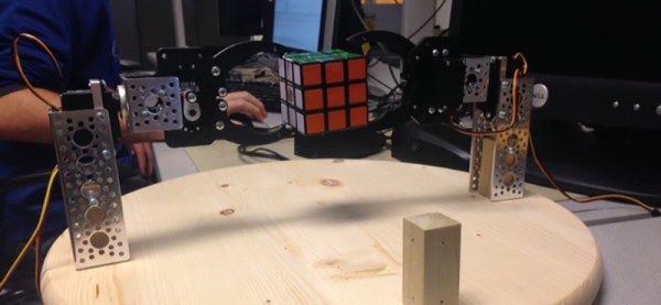
For their final project for ECE 5760 at Cornell, [Alex], [Sungjoon], and [Rameez] are solving Rubik’s Cubes. They’re doing it with an FPGA, with homebrew robot arms to twist and turn a rainbow cube into the correct position.
First, the mechanical portion of the build. The team are using a system of three robot arms positioned on the left, right, and back faces of the cube relative to a camera. When a cube is placed in the jaws of this robot, the NTSC camera data is fed into an FPGA, where a Nios II soft core handles the actual detection of the cube faces, the solver algorithm, and the controller to send servo commands to the robot arms.
The algorithm used for solving the cube is CFOP – solve the white cross, the white corners, the middle layer, the top face, and finally the entire cube. In practice, the robot ended up taking between 60-70 moves. This is not the most efficient algorithm; the Thistethwaite algorithm only requires 52 moves. There’s a reason for this apparent inefficiency – the Thistlethwaite algorithm requires large look-up tables.
Once the cube is scanned and the correct moves are computed, the soft core in sends commands out through the FPGA’s GPIO pins. Each cube can be solved in under three minutes after it has been scanned, but the team ran into problems with scanning accuracy. It’s a problem that can be fixed with the right lighting setup and better aberrant cubie detection, and a great final project using FPGAs.
Video demo below.
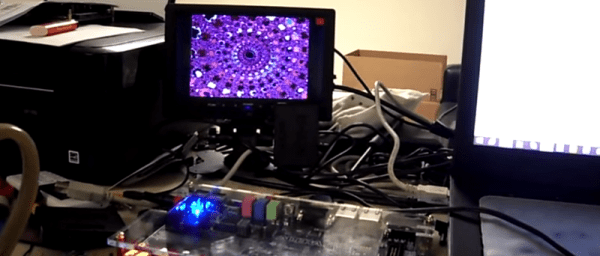
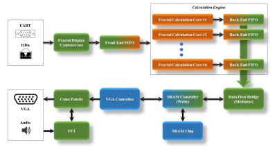 On the FPGA, a custom calculation engine, running at up to 150 MHz, does the math to generate the fractal. A Fast Fourier transform decomposes the audio input into frequencies, which are used to control the colors of the output image.