This excellent content from the Hackaday writing crew highlights recurring topics and popular series like Linux-Fu, 3D-Printering, Hackaday Links, This Week in Security, Inputs of Interest, Profiles in Science, Retrotechtacular, Ask Hackaday, Teardowns, Reviews, and many more.
It’s remarkable how tiny electronics have become. Heaven knows what an old-timer whose experience started with tubes must think, to go from solder tags to SMD in a lifetime is some journey. Even the generation that started with discrete transistors has lived through an incredible shift. But it’s true, SMD components are tiny, and that presents a challenge aside from the one you’ll face when soldering them. Identifying and measuring the value of a chip component too small to have any writing upon it becomes almost impossible with a pair of standard test probes.
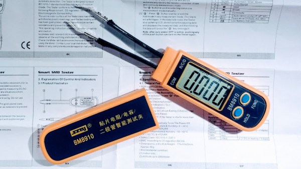
Happily the test equipment manufacturers have risen to the challenge, and produced all sorts of meters designed for SMD work that have a pair of tweezers instead of test prods. When I was looking for one I did my usual thing when it comes to Hackaday reviews. I looked at the budget end of the market, and bought an inexpensive Chinese model for about £16($21). And since I was browsing tweezers I couldn’t resist adding another purchase to my order. I found a pair of tweezer test probes for my multimeter which cost me just over a pound ($1.30) and would provide a useful comparison. For working with SMD components in situ, do you even need the special meter?
Pay no attention to the man behind the curtain. It’s a quote from the Wizard of Oz but also an interesting way to look at our interactions with electronics. The most natural interactions free us from thinking about the ones and zeros behind them. Your next challenge is to build an innovative interface for humans to talk to machines and machines to talk to humans. This is the Human-Computer Interface Challenge!
The Next Gen of HCI
A Human-Computer Interface (or HCI) is what we use to control computers and what they use to control us get information to us. HCIs have been evolving since the beginning. The most recent breakthroughs include touchscreens and natural-language voice interaction. But HCI goes beyond the obvious. The Nest thermostat used a novel approach to learning your habits by observing times and days that people are near it, and when the temperature setting is changed. This sort of behavior feels more like the future than having to program specific times for temperature control adjustments. But of course we need to go much further.
You don’t need to start from scratch. There are all kinds of great technologies out there offering APIs that let you harness voice commands, recognize gestures, and build on existing data sets. There are chips that make touch sensing a breeze, and open source software suites that let you get up and running with computer vision. The important thing is the idea: find something that should feel more intuitive, more fun, and more natural.
The Best Interfaces Have Yet to Be Dreamed Up
No HCI is too simple; a subtle cue that makes sure you don’t miss garbage collection day can make your day. Of course no idea is too complex; who among you will work on a well-spoken personal assistant that puts Jarvis to shame? We just saw that computers sound just like people if you only tell them to make random pauses while speaking. There’s a ton of low-hanging fruit in this field waiting to be discovered.
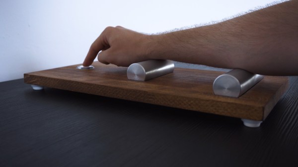
An HCI can be in an unexpected place, or leverage interactions not yet widely used like olfactory or galvanic responses. A good example of this is the Medium Machine which is pictured above. It stimulates the muscles in your forearm, causing your finger to press the button. The application is up to you, and we really like it that Peter mentions that Medium Machine reaches for something that wouldn’t normally come to mind when you think about these interfaces; something that hasn’t been dreamed up yet. Get creative, get silly, have some fun, and show us how technology can be a copilot and not a dimwitted sidekick.
You have until August 27th to put your entry up on Hackaday.io. The top twenty entries will each get $1,000 and go on to the finals where cash prizes of $50,000, $20,000, $15,000, $10,000, and $5,000 await.
Have you tried Altium CircuitMaker? Uh, you probably shouldn’t. [Dave] of EEVBlog fame informs us via a reliable source that CircuitMaker is intentionally crippled by adding a random sleep on high pad-count boards. The hilarious pseudocode suggested on the forum is if ((time.secs % 3) == 0) delayMicroseconds(padCount * ((rand() % 20) + 1));.Now, this is a rumor, however, I would assume [Dave] has a few back channels to Altium. Also, this assertation is supported by the documentation for CircuitStudio, which says, “While there are no ‘hard limits’ per se, the software has been engineered to make it impractical for use with large designs. To this end, the PCB Editor will start to exibit [sic] performance degradation when editing designs containing 5000 pads”. Chalk this up to another win for Fritzing; Fritzing will not slow down your computer on purpose.
Here’s an open challenge to everyone. As reported by [SexyCyborg], XYZPrinting (makers of the da Vinci printer) are patent trolling. This US patent is being used to take 3D printers off of the Amazon marketplace. Here’s the problem: no one can figure out what this patent is actually claiming. There’s something about multiple nozzles, and it might be about reducing nozzle travel, but I’m getting a ‘snap to bed’ vibe from this thing. Experts in 3D printing have no idea what this patent is claiming. The printer in question is the Ender 3, one of the first (actually the third…) China-based Open Source Hardware certified products, and it’s actually the best selling printer on Amazon at this time. I’m talking with Comgrow (the sellers of the Ender 3 on Amazon), and the entire situation is a mess. Look for an update soon.
Like integrated circuits and microprocessors? Sure you do. Like drama? Oh boy have we got the thing for you. A week or so ago, ARM launched a website called RISC-V Basics (now unavailable, even from the Internet Archive, but you can try it here). It purports to settle the record on those new chips based on the capital-O Open RISC-V instruction set. In reality, it’s a lot of Fear, Uncertainty, and Doubt. This was an attempt by ARM Holdings to kneecap the upstart RISC-V architecture, but a lot of ARM engineers didn’t like it.
This is your last weekend to get your project together for the Power Harvesting Challenge in this year’s Hackaday Prize. We’re looking for projects that harvest energy from the ether, and power electronics from solar, thermal, wind, light, or random electromagnetic fluctuations. Is it going to save the world? Maybe, but it’s a great excuse to build some really cool electronics. If you have an idea in mind, this is your last weekend to enter it in the Power Harvesting Challenge.
The Hackaday community has thrown itself full-force into the Hackaday Prize, and there are hundreds of projects entered in this year’s Prize. Next week, we’ll choose the top twenty projects entered during the Power Harvesting Challenge to advance to the finals. Each of those twenty projects will be awarded $1,000 and be in the running to win the Grand Prize of $50,000 and four other top cash prizes.
This is your last chance to get in on the Power Harvesting Challenge in this year’s Hackaday Prize. For this challenge, we’re looking for projects that harvest energy from any source. It could be a module, or as a distinct design easily incorporated into other builds. Don’t wait — start your entry now.
The Power Harvesting Challenge ends a 07:00 AM PDT on July 16th. Afterwards, we’ll be continuing on into Human-Computer Interface and Musical Instrument Challenges. This is your shot to get your project in the finals in the Hackaday Prize. Don’t miss out!
Today’s entry comes to us from [Robert Tomsons], who was kind enough to document this crushing tale of woe so that we might all learn what true heartbreak is. If you’ve ever toiled away at getting that perfect surface finish with body filler, this one is going to hurt. In fact, you might just want to hit that “Back” button and head to safety now. There’s probably a pleasant story about some 3D printed thing being used with a Raspberry Pi of some sort that you can read instead.
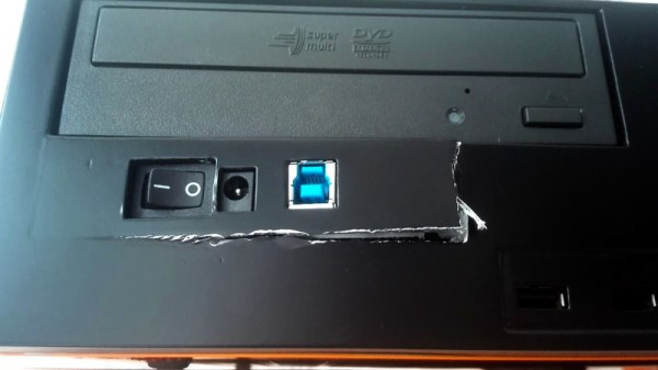
For those of you brave enough to continue on, today we’ll be looking at what [Robert] thought would be a simple enough project. Seeing the board from a USB 3.0 external hard drive kicking around his parts bin, he had a rather unusual idea. Wanting to add an extra drive to his computer, but liking the idea of being able to independently control its power, he decided to integrate the external drive into machine’s front panel. This would not only allow him to power off the secondary drive when not in use, but it meant he could just plug his laptop into the front panel if he wanted to pull files off of it.
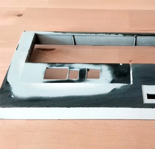
All [Robert] needed to do was make it look nice. He carefully squared off the edges of the external drive’s back panel to roughly the size of the computer’s 3.5 inch drive bay opening. He then glued the piece in place, and began the arduous task of using body filler to smooth everything out. It’s a dance that many a Hackaday reader will know all too well: filler, sand, primer, sand, filler, sand, primer, sand, so on and so on. In the end, the final result looked perfect; you’d never have thought the front panel wasn’t stock.
It should have been so easy. Just snap the case back together and be done with it. But when [Robert] finally got the machine buttoned back up and looked at the front, well, it’s safe to say his day couldn’t get much worse. Maybe the glue was not up to the task. Perhaps it was how excited he was to get the case put back together; a momentary loss of muscular coordination. A few extra foot-pounds of energy per second, per second. Who can say?
Telephone answering machines were almost a fad. They were hindered for years by not being allowed to connect to the phone lines. Then a mix of cell phones and the phone company offering voicemail made the machines all but obsolete. Unless you are really young, you probably had one at some point though. Some had digital outgoing messages and a tape to record. Some had two tapes. But did you ever have one that didn’t connect to the phone line at all? Remember, there was a time when they couldn’t. My family had one of these growing up and after doing enough research to find it in an old catalog, I decided you might like to know how it really worked.
Even if you grew up in the 1960s and 1970s, it is hard to imagine how little technology there was in an average person’s home at that time. You probably had one TV and one wired telephone. You probably had a radio or two and maybe even a record or tape player. If you were very fancy, you had a big piece of furniture that had a TV, a turntable, a radio, and a tape player in it. No cell phones, no computers, no digital assistant, and appliances were electro-mechanical and didn’t have displays. So when you saw a new piece of tech — especially if you were a kid who didn’t know what a hacker was, but still wanted to be one — it made an impression.
I still remember the first time I even saw a tape recorder. I was amazed! But a tape recorder is a far cry from a telephone answering machine.
A Bit of Background
My Dad always had a regular job and his side business. He had a lot of different side businesses at one time or another, but he was always concerned about missing a phone call from a customer. We had two phones: the old wall mount phone with a dial and another desk phone in the “store” (the front room of the house) which also had a dial — we were way too cheap to pay for TouchTone service.
Remember, there was no call waiting and getting a second phone line was out of the question for my frugal parents. So they were always nervous about keeping the phone line clear during the day. But if you had to leave, you might miss a call. What do you do about that?
Shared libraries are our best friends to extend the functionality of C programs without reinventing the wheel. They offer a collection of exported functions, variables, and other symbols that we can use inside our own program as if the content of the shared library was a direct part of our code. The usual way to use such libraries is to simply link against them at compile time, and let the linker resolve all external symbols and make sure everything is in place when creating our executable file. Whenever we then run our executable, the loader, a part of the operating system, will try to resolve again all the symbols, and load every required library into memory, along with our executable itself.
But what if we didn’t want to add libraries at compile time, but instead load them ourselves as needed during runtime? Instead of a predefined dependency on a library, we could make its presence optional and adjust our program’s functionality accordingly. Well, we can do just that with the concept of dynamic loading. In this article, we will look into dynamic loading, how to use it, and what to do with it — including building our own plugin system. But first, we will have a closer look at shared libraries and create one ourselves.

 A Human-Computer Interface (or HCI) is what we use to control computers and what they use to