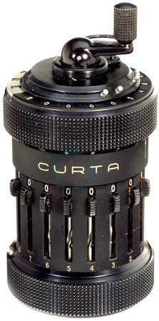
The CURTA mechanical calculator literally saved its inventor’s life. [Curt Herzstark] had been working on the calculator in the 1930s until the Nazis forced him to focus on building other tools for the German army. He was taken by the Nazis in 1943 and ended up in Buchenwald concentration camp. There, he told the officers about his plans for the CURTA. They were impressed and interested enough to let him continue work on it so they could present it as a gift to the Führer.
This four-banger pepper mill can also perform square root calculation with some finessing. To add two numbers together, each must be entered on the digit setting sliders and sent to the result counter around the top by moving the crank clockwise for one full rotation. Subtraction is as easy as pulling out the crank until the red indicator appears. The CURTA performs subtraction using nine’s complement arithmetic. Multiplication and division are possible through successive additions and subtractions and use of the powers of ten carriage, which is the top knurled portion.
Operation of the CURTA is based on [Gottfried Leibniz]’s stepped cylinder design. A cylinder with cogs of increasing lengths drives a toothed gear up and down a shaft. [Herzstark]’s design interleaves a normal set of cogs for addition with a nine’s complement set. When the crank is pulled out to reveal the red subtraction indicator, the drum is switching between the two sets.
Several helper mechanisms are in place to enhance the interface. The user is prevented from ever turning the crank counter-clockwise. The crank mechanism provides tactile feedback at the end of each full rotation. There is also a lock that disallows switching between addition and subtraction while turning the crank—switching is only possible with the crank in the home position. There is a turns counter on the top which can be set to increment or decrement.
You may recall seeing Hackaday alum [Jeremy Cook]’s 2012 post about the CURTA which we linked to. A great deal of information about the CURTA and a couple of different simulators are available at curta.org. Make the jump to see an in-depth demonstration of the inner workings of a CURTA Type I using the YACS CURTA simulator.
Continue reading “Retrotechtacular: The CURTA Mechanical Calculator”
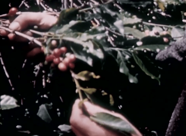
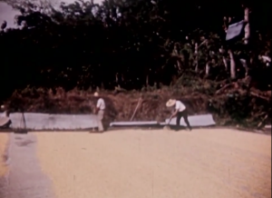 The day’s harvest is collected, weighed, and bagged for further production. The fruits are crushed to remove each bean from its red jacket. Then, the beans are washed and spread out in the sun for 8-10 days. They are frequently rotated so they dry evenly. The dried coffee is packed in bags and sent into the city.
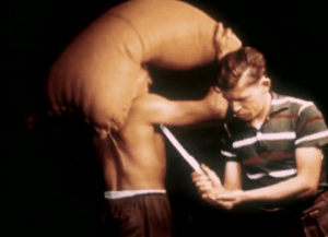 At a warehouse, the coffee is inspected, sorted, and graded. Bags are stamped with the coffee’s country of origin and intended destination before going to the seaport. A very important step happens here. As each bag walks by on the shoulders of a worker, another guy stabs it to get a sample of the beans. The on-site A&P officials take over at this point and do their own inspections, sending samples to the US. Here, the coffees are roasted and taste tested for both strength and flavor from a giant lazy Susan full of porcelain cups.
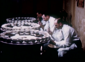
 Chances are, you take color for granted. Whether or not you give it much thought, color is key to distinguishing your surroundings. It helps you identify fire, brown recluse spiders, and the right resistor for the job.
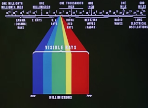 Each color that makes up the spectrum of visible rays has a particular wavelength. The five principal colors—red, yellow, green, blue, and violet—make possible thousands of shades and hues, but are only a small slice of the electromagnetic spectrum.
 We’ve probably all experimented with a very clear demonstration of the basic principles of lift: if you’re riding in a car and you put your flattened hand out the window at different angles, your hand will rise and fall like an airplane’s wing, or airfoil. This week’s Retrotechtacular explains exactly how flight is possible through the principles of lift and drag. It’s an Army training documentary from 1941 titled “
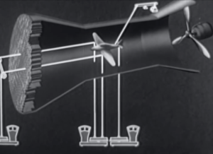
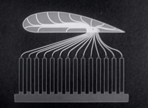 Airfoil models are also unit tested in wind tunnels. They are built with small tubes running along many points of the foil that sit just under the surface. The tubes leave the model at a single point and are connected to a bank of manometer tubes. These tubes compare the pressures acting on the airfoil model to the reference point of atmospheric pressure. The different liquid levels in the manometer tubes give clear proof of the pressure values along the airfoil. These levels are photographed and mapped to a pressure curve. Now, a diagram can be made to show the positive and negative pressures relative to the angle of attack.