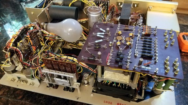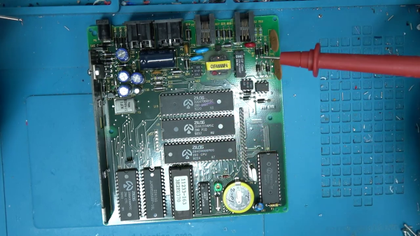
[Ben Heck] found an old card-swipe point-of-sale box at the Goodwill store, took it home, and tore it down to see what was inside. He found a completely serviceable single board computer based on the Z80. In fact, there’s a whole family of four Z80 chips: the CPU itself, the DART chip (dual UART), the PIO chip (parallel input/output interface), and the CTC chip (counter/timer circuit). That’s not all — there’s a landline telephone modem, a real time clock, 32K of RAM and UV-EPROM. The second PCB of this assembly holds a hefty sixteen-key keypad and a sixteen-character vacuum fluorescent alphanumeric display. All this for the bargain price of $2.99.
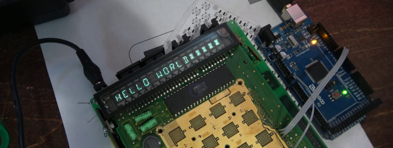
Surely [Ben] will dig into the Z80 system in the future, but in this video he tries to make the display work. An OKI Semiconductor controller drives the VFD. After tracking down the data sheet, [Ben] wires it up to an Arduino and writes a quick program. Only a few YouTube minutes later, he conquers the display, drawing sample text anywhere he wants on the screen with any brightness he desires.
You never know what you may find lurking inside old equipment like this. You might find a proprietary ASIC with no documentation, or like [Ben] did here, you could find a fully functioning embedded computer. If [Ben] can whip up a RAM-based emulator to replace the 32K UV-EPROM, he’ll have a perfect evaluation board for Z80 projects.
Let us know in the comments if you have found any treasures like this. Also, how would you use this board if you had found it? Thanks to reader [Nikša Barlović] for sending in the tip.
Continue reading “Z80 Family Reunion Discovered In Old PoS Card Swiper”